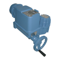
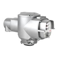
AUMA Matic Positioner
Calibration Instruction
AUMA Actuators, Inc. USA
All information in this document is subject to change without notice.
Setting of the Sensitivity
• Set selector switch at local controls (Figure 1, Page 2) to position REMOTE.
• Input a random command signal E1. The sensitivity (∆E / dead band) is set to maximum value (2,5 %) in the
factory.
• The sensitivity can be improved or the dead band reduced by turning potentiometer ∆E (P9) clockwise. For a
precise setting of the sensitivity, a set point device with accuracy in the 0,1 mA range is required.
• For actuators with a speed of 19 rpm or less, a better sensitivity (∆E
min
= 0.25 %) can be achieved by turning
the potentiometer P7 (sens) clockwise.
NOTE: When setting ∆E the following must be observed: If the number of starts is too high, this will
lead to unnecessary wear at the valve and actuator. Therefore, the maximum possible dead band
acceptable for the process must be set. .
• To prevent exceeding the max. permissible number of starts (refer to Technical data sheet SG,SAR or
consult factory) in extreme cases, a time delay between 0.5s (left stop) and 10s (right stop) may be set with
potentiometer t-off.
Positioner Adjustment End Position OPEN (inverse operation)
In standard version the maximum input signal (E1 = 20 mA) results in operation to end position OPEN.
• By switching the code switch S3-7 (Figure 4) to position ”1” an inversion of this signal definition (inverse
operation) can be achieved.
• Additionally, the potentiometer wiring at actuator terminals TA 20 and 21 must be reversed.
NOTE: Prior to the positioner setting it has to be ensured that the limit and torque switching of the
actuator as well as the position feedback have been set.
• Set selector switch (local controls) to position LOCAL.
• Run actuator with push-button to end position OPEN.
• Supply nominal value E1 of 0 or 4 mA (see wiring diagram).
• Turn potentiometer P10 (t
off
) counter-clockwise up to the stop (Figure 3).
NOTE: Missing signals E1/ E2 or wrong polarity are indicated by LED V10 ”E1/E2 < 4 mA” (Figure 3).
ISSUE 02/02 Page 7 of 11 SE-SI-35-0007
 Loading...