4. Insert the plug of the back motor into the
control box at the connection point on the
side (connection point 4).
5. Insert the plug of the upper leg motor into
the control box at connection point 1.
6. Insert the plug of the remote control into
the control box at connection point 2.
7. Insert the plug of the head support into the
control box at connection point 3.
8. Secure the cords underneath the pull relief
on the control box.
9. Insert the plug of the control box into the
wall socket.
3.3 Connecting the head support motor
Connect the coiled flexible cable of the pre-
mounted head support motor to the side of
the electric motor for the back section and
foot end. Lead the cable over the cross bar of
the adjusting mechanism of the back section,
giving the cable enough play to follow the
movement of the back section.
3.4 Attachment of the handset
• In order to easily attach
the handset to the
Auping Auronde and
Next or other bed
model.
• Place the clamp on the
underside of the side
panel of the surround
(see fig. 4).
• Click the handset into
the clamp.
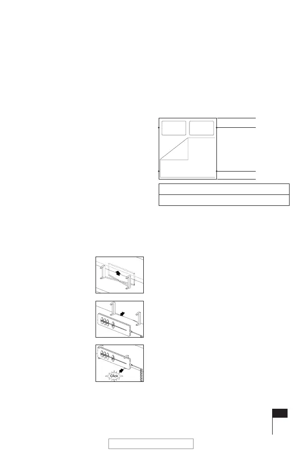
3.5 Position of the legs
Correct placement of the legs is essential for
a correct weight distribution. This means that
the legs must be placed at the distances from
head and foot end of the bed as indicated in
the following illustration (bed seen from
above):
GB15
fig. 4
Hoofdeind (HE)
Voeteneind (VE)
Lengte 190/200 cm: HE 20 cm VE 25 cm
Lengte 210/220 cm: HE 30 cm VE 25 cm
_006IH_3114 BW.pdf - pag.15
November 9, 2007
LET OP !!! Lage resolutie!