37
2. When you are off the network, tap the position of the indicator of the sound control switch, and the
background indicator of the LCD is on. If you do not operate the LCD any more, the background indicator is
off 2 minutes later and the LCD returns to the default time display.
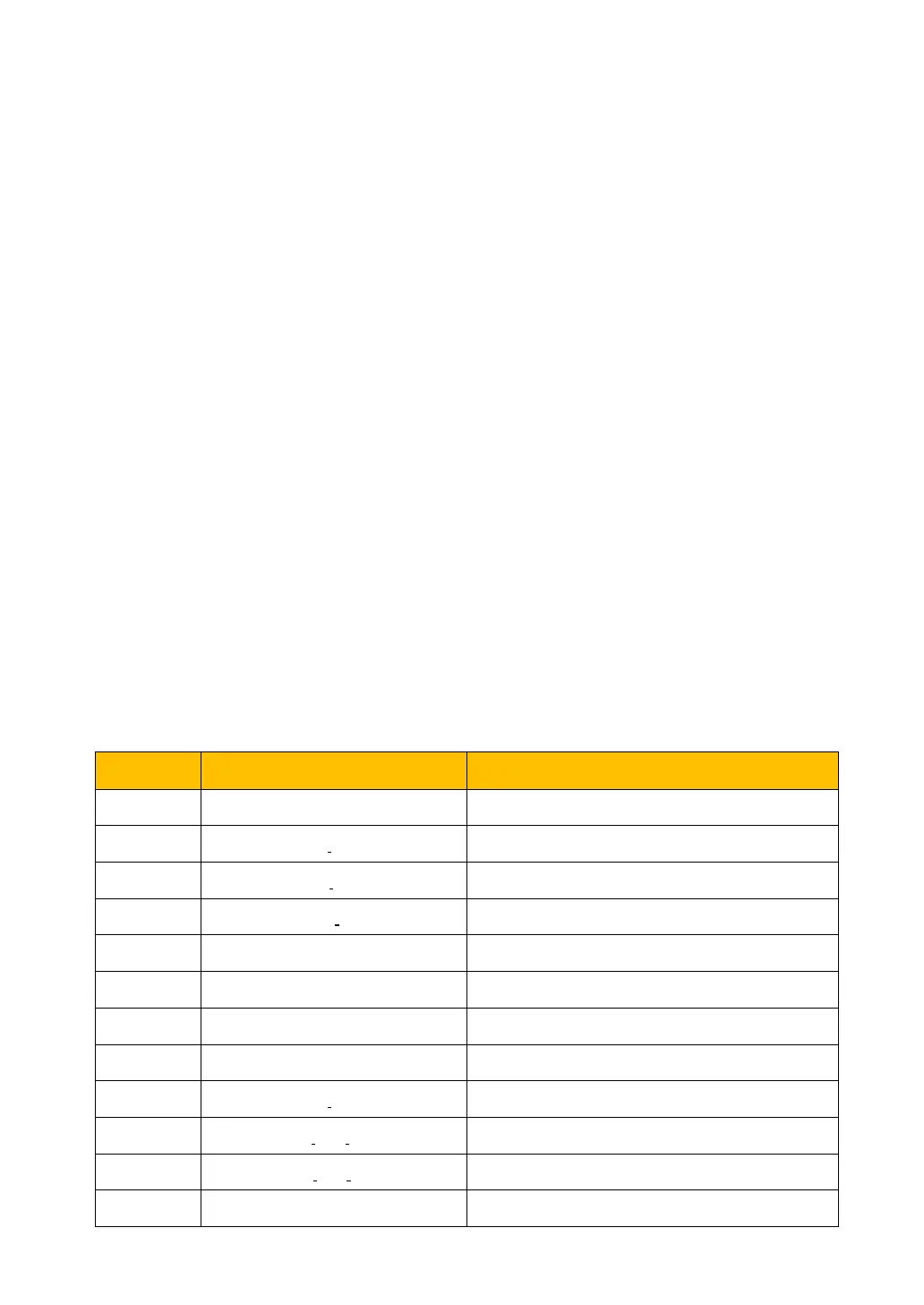
3.Error Info Common fault codes are described in Table 5-1.
● Standby mode
After operation, the inverter changes from operation mode to standby mode if the current on the DC side
is very small (approximate to 0 A) and remains there for 20 seconds. In standby mode, the inverter
constantly detects whether the PV arrays has enough energy to connect to the grid for power generation.
When it reaches 300V (hold for 20 seconds), the inverter transfers from standby mode to operation
mode.
When the inverter starts, it will countdown for 20 seconds. If the inverter counts down for 5 times in a row
within 15 minutes, the system considers that the startup conditions are unstable and not suitable for the
grid-connected operation of the inverter. The inverter will re-check whether the startup conditions meet
the requirements after 30 minutes.
Note: The display mode in standby mode and fault mode is the same as that in normal mode, but the
specific parameters (electric quantity, temperature, current, etc.) are different in different modes. The
data displayed on the display is real data.
Failure mode
When the PV power generation system fails. The inverter will stop working and the relay on the AC side
will be immediately disconnected; The main circuit of the inverter is disconnected from the power grid. At
this time, the system continuously monitors whether the fault is eliminated. If the fault is not eliminated,
the fault state is maintained. If the fault is eliminated, reconnect the grid after the 20 seconds countdown.
Table 5-1 lists the fault modes displayed on the screen.
The AC phase sequence is faulty
Leakage current is over limit
Leakage current fluctuation is over limit


 To Next Page