* TTL stands for Transistor-Transistor Logic, a +5/0 volt standard for representing
on and o – used by the ValveLink8.2 for computer valve control.
Introduction
FOR RESEARCH USE ONLY
The ValveLink8.2 is designed for solution-switching use in research
applications ONLY. AutoMate Scientic, Inc. cannot be responsible for
injury or death resulting from medical or pharmacological use.
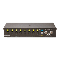
Hardware Overview
The ValveLink8.2
®
is a digital/manual valve controller designed for use
with research automation software. Valves can be controlled by digital
TTL* signals from any I/O card or device or a single analog voltage input.
Eight pushbuttons allow manual user control with eight bi-colored LED
indicators. A USB (Universal Serial Bus) port is provided for further valve
control and networking by computer. All four input sources (digital,
analog, USB, and pushbuttons) are simultaneously active, and the LEDs
constantly display the current valve status. ValveGuard
™
technology
detects bad valves. It prevents damage to your ValveLink8.2 and let's you
easily observe problem valves. A spill sensor protects your equipment
when a leak is detected.
The ValveLink8.2 is designed to drive 12 volt DC solenoid valves plugged
into RCA jacks on the back of the box. Why not connect valves directly to
your computer? Several reasons:
1) Most computer interfaces provide +5V signals – not strong enough
to drive most valves (6 to 12V DC and higher).
2) Computer interface signals are often too noisy for
electrophysiology amplication. The ValveLink8.2 is designed
with special low-noise circuitry to minimize interference with
high-gain amplication.
3) Finally, many solenoid valves are designed to be opened with a
short, full-voltage pulse, then “held-in” with a lower voltage to
keep the valves from heating. The ValveLink8.2 automatically
provides dual-voltage hold-in.
Chromatography
Gel/Blot Washing System
Operation
.................................................................................. 17
Manual Control
Digital Inputs
Digital Input Port Pin-out
Analog Input
Simultaneous Edge-triggered Inputs
LED Indicators and ValveGuard
™
Event Marker
Spill Sensor
Where is the power switch? Sleep
3-way Valves
Back Panel
Power Supply
Case and Valve Grounding
Modes
.......................................................................................24
Mode Descriptions
Multiple Modes
USB Communications & Software
..........................................27
Installation
Software Operation
Computer Interfacing ...............................................................32
Techniques ................................................................................ 34
Dead Volume
Small-bore PTFE Tubing
Backow
AutoPrime
™
System
Faulty Valves
Stuck Pinch Valves
Valve Cables
Valve Returns & Replacing a Valve
Leaks and Replacing Valve Fittings
Hardware Troubleshooting
Safety Instructions ...................................................................40
Warranty ...................................................................................42
Table of Contents Continued
 Loading...