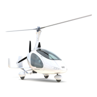
Pilot Operating Handbook
Cavalon
SECTION 7
SYSTEM DESCRIPTION
AutoGyro_POH_Cavalon 915iS Revision 1.0 – Issue Date 08.MAY.2019 7-17
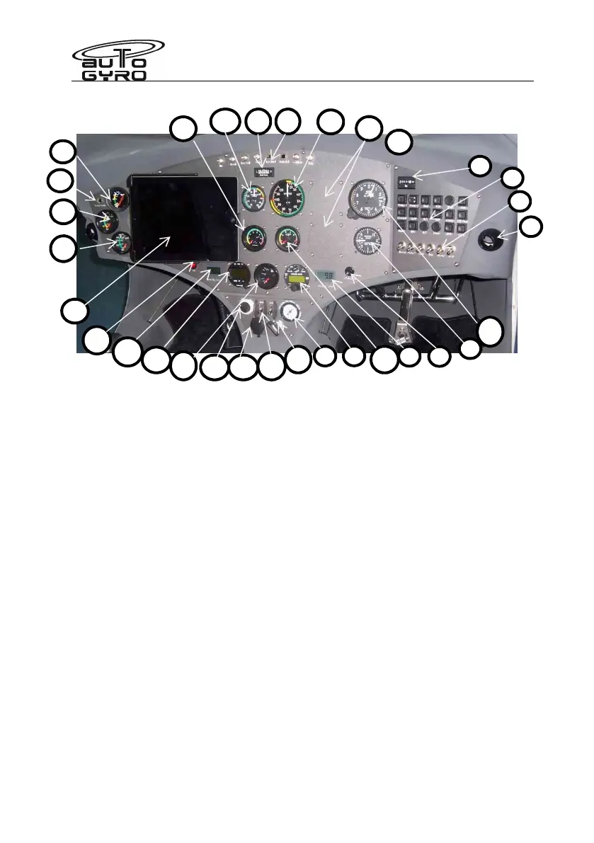
1 – Hour meter 17 – Fuel level indicator
2 – Circuit Breaker Panel 18 – Cylinder head temperature
3 – Air outlet 19 – Oil pressure
4 – Switches (2
fuel pump, lights, optns.) 20 – Oil temperature
5 – Pre-rotator overdrive/override 21 – Engine RPM
6 – OAT indicator 22 – Rotor RPM
7 – Radio (if installed) 23 – Lateral trim indicator
8 – Cut-out 57mm / 2 ¼” for optional inst. 24 – Warning and Caution Panel
9 – Trim/brake pressure gauge 25 – Manifold pressure gauge (if inst.)
10 – Master/starter switch 26 – Air speed indicator
11 – LANE switches 27 – Attitude Indicator or VSI (if installed)
12 – 12V power receptacle (if installed) 28 – Altimeter
13 – Pneumatic mode selector 29 – Water temp (if fitted).
14 – ATC transponder (if installed) 30 – Not assigned
15 – RBT indicator 31 – Not assigned
16 – Cooling fan manual activation 32 – Ipad (if fitted)
electronic altimeter and air-speed indicator manufactured by Auto-Gyro are
available as alternative fitments to the conventional barometric devices. These electronic
instruments are configurable for different units (e.g. knots, mph, km/hr) and have coloured
limitations markings applicable to the aircraft type. If fitted a User Manual is provided.
These may be fitted to any day VFR panel (not night and day VFR)
23
25
24
26
12
11
10
22
32
16
15
14
17
13
21
20
19
18
28
29
27
26