Pilot Operating Handbook
Cavalon
SECTION 7
SYSTEM DESCRIPTION
AutoGyro_POH_Cavalon 915iS Revision 1.0 – Issue Date 08.MAY.2019 7-18
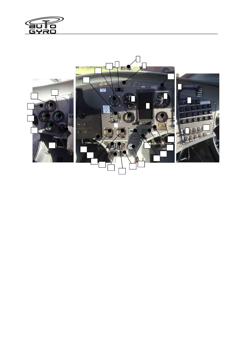
1 – Magnetic compass 20 – Static port switch
2 – Warning lights 21 – Radio (if installed)
3 – Lateral trim indicator 22 – Audio in (if installed)
4 – Air speed indicator 23 – OAT indicator
5 – Altimeter 24 – Overdrive/rotor brake interlock releas
6 – Aspen PFD 25 – Pneumatic mode selector
7 – Hour meter 26 – LANE switches
8 – Circuit Breaker Panel 27 – Trim/brake pressure gauge
9 – Switches (avionic and 2
fuel pump) 28 – 12V power receptacle
10 – Switches (options) 29 – Master/starter switch
11 – Water temperature indication 30 – Clock
12 – Cooling fan manual activation 31 – Propeller controller.
13 – Manifold press gauge 32 – Rotor rpm gauge
14 – ATC transponder (if installed)
15 – Oil pressure gauge
16 – Fuel pressure gauge
17 – Oil temp gauge
18 – CHT or coolant temp gauge
19 – Panel light dimmer
33 – Fuel level gauge
8
1
2
3
4
5
6
7
9
10
11
12
13
14
15
16
17
18
19
20
21
22
23
24
25
26
27
28
29
31
32
33
30
8