Revised 4/3/00 • M220nx 7 © 2000 Automated Logic Corporation
compare it to the condition reported on
the FB’s Status page.
Digital Outputs
TheM220nxmodulehastwodigitaloutputs
which can be connected to a maximum of 24
Volts AC/DC. Each output is a dry contact
(rated at 3A maximum) that is normally open.
Be sure the M220nx’s power is off before
wiring any inputs or outputs. Connect the
output wiring to the screw terminals on the
module as shown in Figure 6.
NOTE Donotpowerpilotrelaysfromthe
same transformer that powers the M220nx.
To verify each output’s operation, lock the
output to a known condition using the
Function Block’s Parameter page, then make
sure the equipment actually operates as
specified.
Each digital output can be placed in Manual
or Auto mode by setting the HOA switches
(see Figure 1 on page 2 for the switches’
location). You can monitor the status of the
HOA switches through SuperVision by
assigning each switch a digital input in the FB
using channel numbers 81 and 82.
An off status on these channels means the
HOAswitchisinAutomode.Anonstatus
means the HOA switch is in Manual mode.
Channel Numbers
The following tables show the valid channel
numbers for each point on the M220nx. Enter
the channel number, offset, and gain for each
point in Eikon before the Function Block is
made, or on the FB’s Parameter page in
SuperVision. If an offset and gain are not
provided here, use SuperVision’sPoint
Configuration or Point Help feature to
determine the offset and gain.
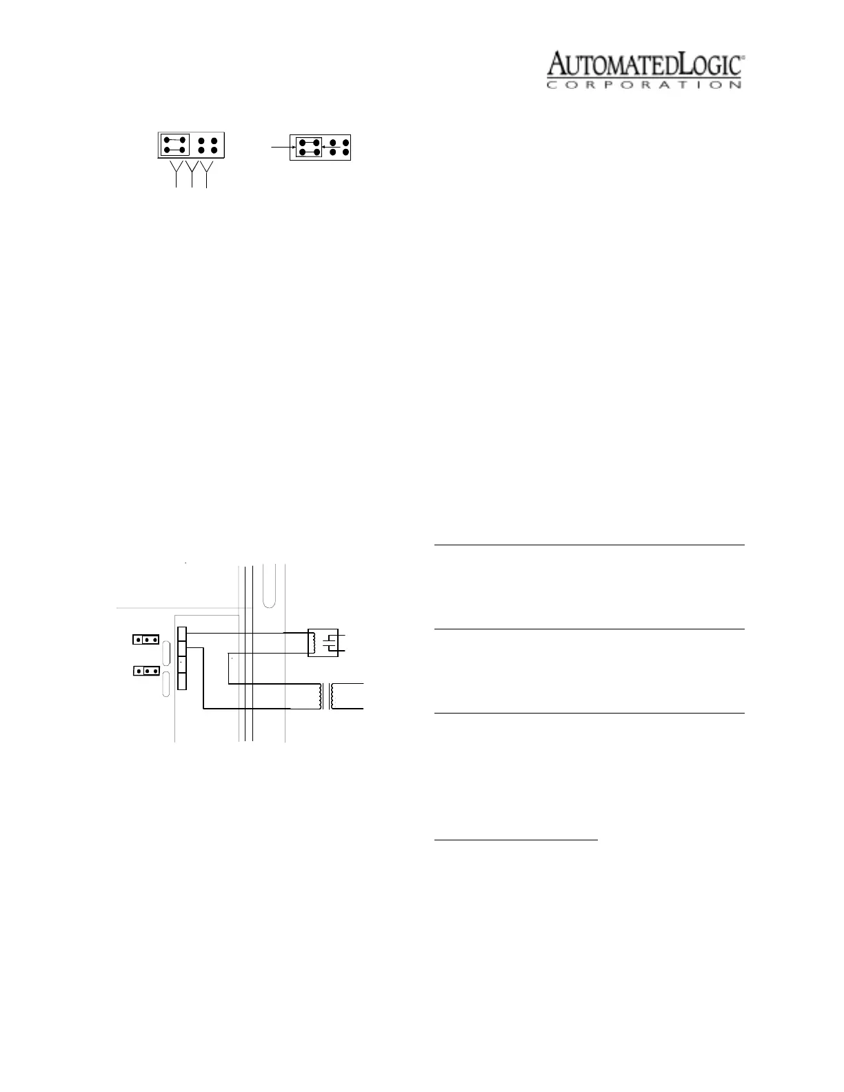
Figure 5. Jumper Position
Figure 6. Digital Output Wiring
Grip
Here
0-20 mA
0-5 VDC
Thermistor/
dry -contact
Universal Input
Mode Select
DRY
CONTACT
24VAC
B
A
B
A
Table 3. Input Channel Numbers
Point Signal Type
Channel
Number †Range Offset Gain
UI 1
Thermistor 31
-17° to 213° F
-27° to 100.6° C
0.00
0.00
15.88
15.69
mA or Volts 31
0 to 20mA
0to5V
§§
Digital 21
UI 2
Thermistor 32
-17° to 213° F
-27° to 100.6° C
0.00
0.00
15.88
15.69
mA or Volts 32
0 to 20mA
0to5V
§§
Digital 22
† Celsius values can only be displayed in SuperVision when the Function
Block is made in Eikon v2.0 or later with the Metric option enabled. Refer to
the Eikon User’s Guide for more information.
§ Use the Point Configuration or Point Help feature in SuperVision v2.0 or
later.
Table 4. Digital Output Channel Numbers
Point Signal Type
Channel
Number
DO 1
Digital
HOA Status†
11
81
DO 2
Digital
HOA Status†
12
82
† Use a digital input microblock to
monitor the status of HOA Switches.
 Loading...