4
Rev. (30-JAN-98) • RLM v4.7 © 1995-98 Automated Logic Corporation
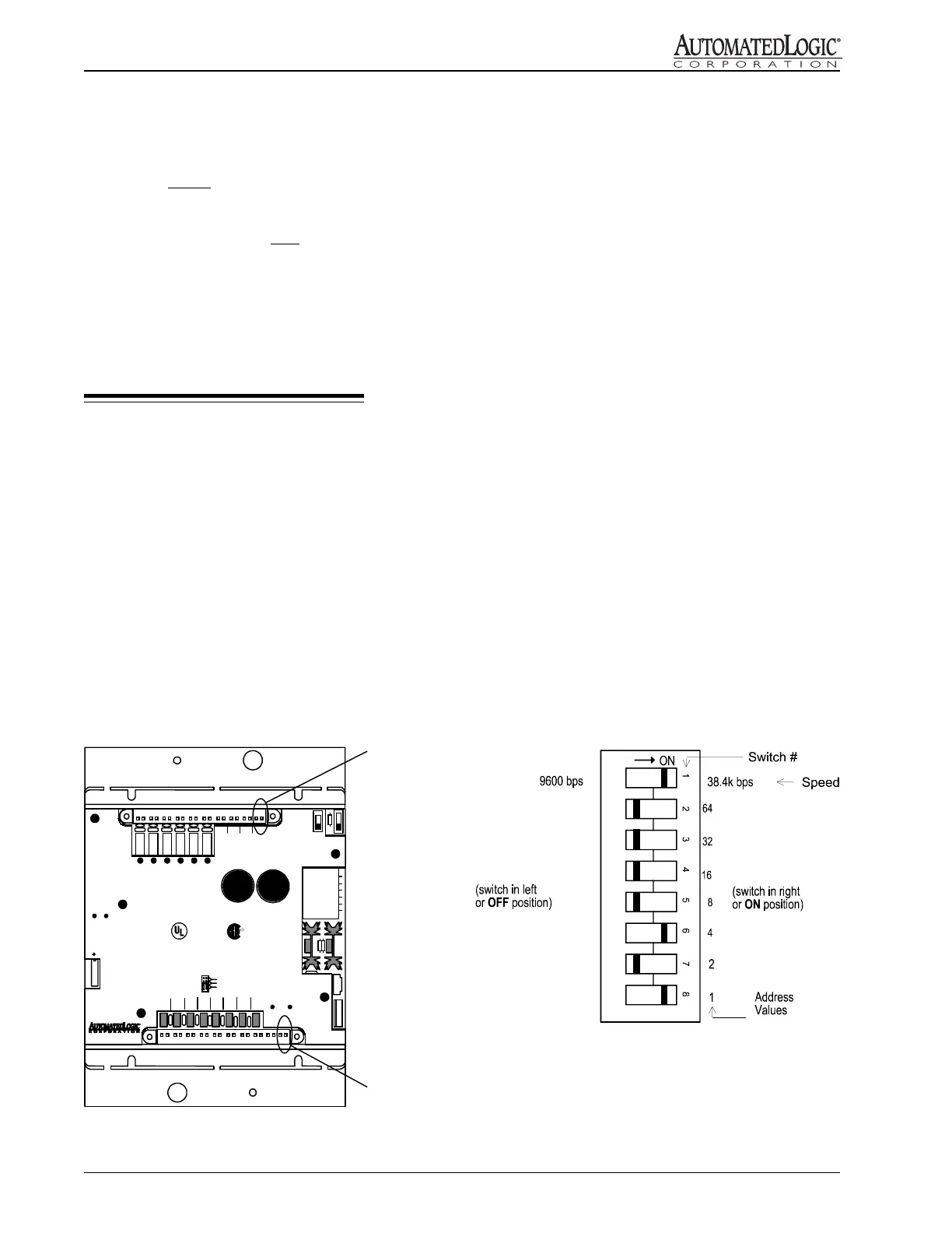
2. Set the module's address using the 8-position DIP
switch (see Figure 1 for switch location).
3. Replace the R683's power jumper.
Setting the Module's Address
The address DIP switch (see Figure 4) is configured with
eight individual sliding ON/OFF switches. Switches 2-8
are used for addressing. The value of each switch is
indicated to the right of the individual switch on the
module cover and in Figure 4. The module's address is
the sum of the values of the switches in the ON position.
As shown in the example, switches six and eight,
counting top to bottom, are in the ON position.
Therefore, this module's address is five.
Setting the CMnet Baud Rate
NOTE: The CMnet baud rate must be the same for all
modules on the CMnet.
Switch 1 (top switch) is used to determine the R683
module's communication speed. When the switch is in
the OFF position, the R683 has a baud rate of 9600 bps.
When the switch is in the ON position, the module has a
baud rate of 38.4k bps.
As shown in Figure 4, switch 1 is set to the right and is in
the ON position. Therefore, the module's baud rate is set
at 38.4k bps.
Figure 4: Setting the Address and Baud Rate
(Address = 5, Baud Rate = 38.4k bps)
5. Terminate the two power wires to the power terminals
labeled Gnd and 24 VAC (see Figure 3 for location).
6. Verify that 24 VAC is present at the power input.
NOTE: Before turning the power on, see
“Addressing and Baud Rate” later in this document.
An error condition will occur if the address of the
R683 module is changed after applying power. If
this happens, memory must be transferred to the
module before operation may resume.
7. After verifying the module's address, turn the R683's
power switch ON and verify that the "Run" LED is
blinking.
Addressing & Baud Rates
NOTES:
1. Before setting or changing the address or baud rate,
remove power from the module.
2. After changing the address, the Error LED may light
when the module is turned ON. You must transfer
memory to the module as described later in this
document to turn this LED off.
Procedure
1. Before setting or changing the address or baud rate,
remove the R683's power jumper.
Figure 3: Power and CMnet Terminals
CAUTION:
To Re du c e the Ris k
of Fi re or E lec tric Shock,
Do Not Interconnect The
Ou tp ut s of D i f ferent Class 2
Circ u its
IN7
A B
IN6
A B
IN5
A B
IN4
A B
IN3
A B
IN 2
A B
-
+
ACCESS
ZONE
R683
CMnet
tr an smi t
receive
IN8
A B
Thermistor/
dry-contact
0-5Vdc
0-20mA
Universal Input
Mode Select
CONTROL MODULE
0 +
DO1
A B
24V Gnd
Power
on
off
Power
Speed
64
32
16
8
4
2
1
CMnet
Ad dr es s
ac
Class 2
50-60Hz
0.83A
Us e Co p p e r
Conducto rs Only
Class 2
50-60 H z
3A Max.
Enclosed Energy
Ma na geme nt Equipme nt
LISTED
88FO
R
AC Power
Terminals
CMnet
Terminals
R
error run
ON
OFF
AUTO
DO2
A B
DO3
A B
DO4
A B
DO5
A B
DO6
A B
-
+
AO1AO2 AO3
-
+
-
+
IN1
A B
 Loading...