6
Rev. (30-JAN-98) • RLM v4.7 © 1995-98 Automated Logic Corporation
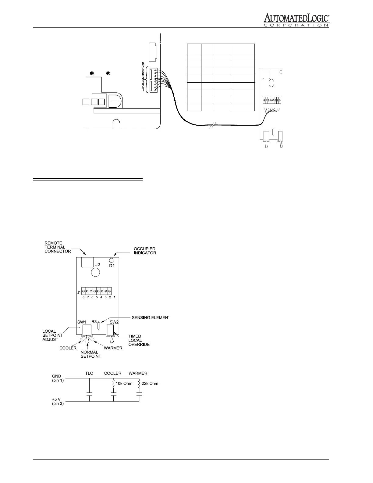
Local Setpoint Adjust
Use the sensor's left switch to adjust the occupied
setpoints. When this switch is placed in the middle
position, the setpoints specified on the RLM FB
parameter page are in effect. The switch's left position
lowers the setpoints by an amount specified on the
parameter page (default is 3 degrees). The switch's right
position raises the setpoints by the same amount.
Timed Local Override
Use the sensor's right switch to activate the zone override.
The switch is spring loaded and always returns to the
right position. This switch has no effect when the zone is
scheduled occupied. When the zone is scheduled
unoccupied, toggling the switch causes the zone to
become occupied. The amount of override time is equal
to the number of times the override switch is toggled
multiplied by the "override increment per toggle"
parameter as defined on the parameter page. For example,
if the increment is set at 60, toggle the switch once for an
occupancy of 60 minutes, twice for 120 minutes, etc.
Once the zone is occupied from this switch, pressing it
again and holding it in the left position for the reset
interval (three seconds default) causes the zone to
become unoccupied.
Occupancy Indication
The LED on top of the sensor lights up whenever the
zone is occupied, whether from a regular schedule, the
action of the Local Override Switch, or an telephone
override.
NOTE: Pins 4 and 7 must be connected to utilize the
occupancy indicator.
Using the Enhanced Zone Sensor
Shown in Figure 8, the enhanced zone sensor provides
local setpoint adjust, timed local override, and
occupancy indication.
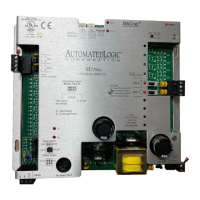
Figure 8: Enhanced Zone Sensor Connection
Figure 7: Enhanced Zone Sensor Wiring
8 7 6 5 4 3 2 1
J1
SENSOR
TERM
1
2
3
4
5
6
7
8
MODULE
TERM
WIRE
COLOR
FUNCTIO N
1
2
3
4
5
6
7
8
BLACK
BROWN
RED
ORANGE
YELLOW
GREEN
BLUE
WHITE
GND
THERMISTOR
SWITCH INPUT
RSZ+ LED
+ COMM
- COMM
5V+, LED Power
NOT USED
RSZ+
CMnet
+
-
ACCESS
R683 module
Note:
When making a sensor cable, disregard the
numbers imprinted on the plastic connector.
 Loading...