DPM1 User Manual, 1st Edition
User Manual - DPM1 Series Panel Meters
9
This instrument conforms with the following community directives: EMC 2004/108/CE and
LVD 2006/95/CE.
Refer to the instructions in this manual to preserve safety protections.
WARNING: If this instrument is not installed and used in accordance with these
instructions, the protection provided against hazards may be impaired.
To meet the requirements of EN 61010-1 standard, where the unit is permanently connected to
main supply, it is obligatory to install a circuit breaking device easily reachable by the operator
and clearly marked as the disconnecting device.
To guarantee electromagnetic compatibility, the following guidelines should be kept in mind:
• Power supply wires should be separately routed from signal wires and never run in the same conduit.
• Use shielded cable for signal wiring.
• Cables section should be ≥0.25 mm².
Before connecting signal wires, signal type and input range should be verified to be within the
right limits. Do not connect simultaneously more than one input signal to the meter.
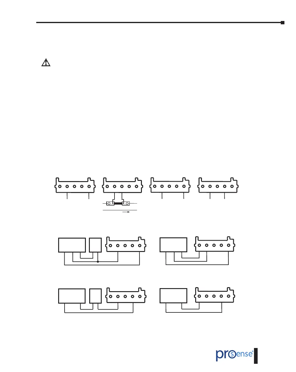
Wiring Examples
±60V DC INPUT
5 4 3 2 1
CN2
-
+
±100mV DC
Shunt INPUT
5 4 3 2 1
I
-
+
CN2
±20mA DC INPUT
5 4 3 2 1
CN2
-
+
Active loops
±10V DC INPUT
5 4 3 2 1
CN2
-
+
Active signals
±10V DC INPUT
5 4 3 2 1
CN2
Connection to transducer
with external excitation
TRANSDUCER
-
+Exc +Out
EXC.
EXT.
-
+
±20mA DC INPUT
5 4 3 2 1
CN2
Connection to transducer
with external excitation
TRANSDUCER
+Exc +Out
EXC.
EXT.
-
+
±10V DC INPUT
5 4 3 2 1
CN2
Connection to transducer with
excitation supplied by DPM1
TRANSDUCER
-
+Exc +Out
±20mA DC INPUT
5 4 3 2 1
CN2
Connection to transducer with
excitation supplied by DPM1
TRANSDUCER
+Exc +Out
For other transducer connection types, do not forget to also join indicator common (CN2, pin 4) to the
negative terminal from the external excitation if it is needed.
 Loading...