9-02 = 5 (8 data bits, odd parity, 1 stop bit)
Communication Protocol
ASCII Mode:
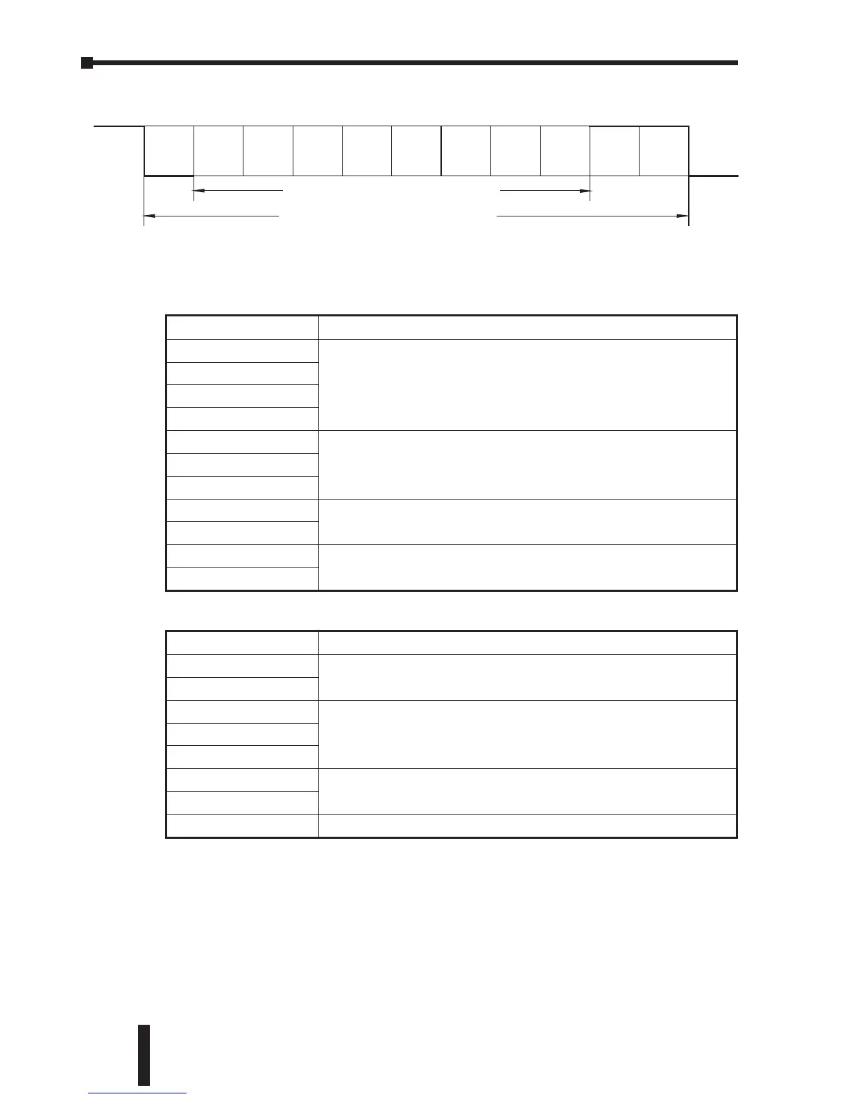
RTU Mode:
ADR (Communication Address)
Valid communication addresses are in the range of 0 to 254. Communication
address equals to 0 means broadcast to all AC drives (AMD), in this case, the
AMD will not reply any message to the master device.
For example, communication to AMD with address 16 decimal:
ASCII mode: (ADR 1, ADR 0)='1','0' => '1'=31H, '0'=30H
RTU mode: (ADR)=10H
Chapter 5: GS1 MODBUS Communications
GS1 Series AC Drive User Manual
5–18
STX Start Character: (3AH)
ADR 1
Communication Address: 8-bit address consists of 2 ASCII codes
ADR 0
CMD 1
CMD 0
DATA (n-1)
Contents of data: n x 8-bit data consists of 2n ASCII codes. n[]25
maximum of 50 ASCII codes
.......
DATA 0
LRC CHK 1
LRC check sum: 8-bit check sum consists of 2 ASCII codes
LRC CHK 0
END 1
END characters: END 1=CR (0DH), END 0 =LF (0AH)
END-0
START A silent interval of more than 10 ms
ADR
Communication Address: 8-bit address
CMD
DATA (n-1)
Contents of data: n x 8-bit data,n<=25.......
DATA 0
CRC CHK Low
CRC check sum: 16-bit check sum consists of 2 8-bit characters
CRC CHK High
END A silent interval of more than 10 ms
 Loading...


