Chapter 2: Installation and Wiring
GS1 Series AC Drive User Manual
2–10
Control Terminal Wiring (Factory Settings)
Note: Use twisted-shielded, twisted-pair or shielded-lead wires for the control signal
wiring. It is recommended to run all signal wiring in a separate steel conduit. The shield
wire should only be connected at the AC drive. Do not connect shield wire on both ends.
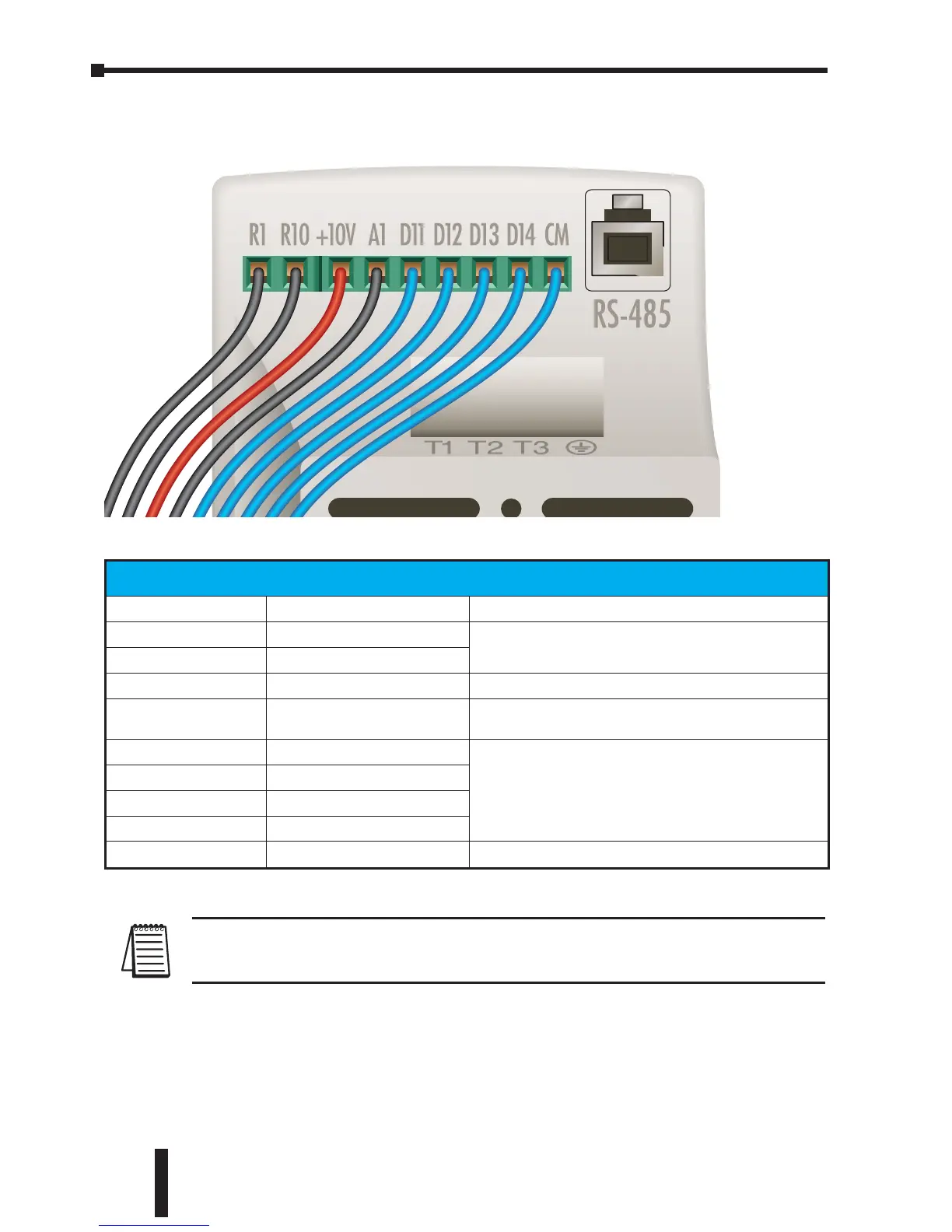
GS1 Bottom View
Control Circuit Terminals
Terminal Symbol Description Remarks
R1
Relay Output Common
120VAC/24VDC @5A,
230VAC @2.5A
R1O
Relay Output Normally Open
+10V
Internal Power Supply +10VDC
AI
Analog Input
0 to +10 V (Max. Output Frequency) Input or
4 to 20mA (Max. Output Frequency) Input
DI1
Digital Input 1
See “Basic Wiring Diagram” on next page.
DI2
Digital Input 2
DI3
Digital Input 3
DI4
Digital Input 4
CM
Common
 Loading...


