Page 2–12 SureServo2 User Manual – 1st Edition – 05/20/2021
Chapter 2: Installation
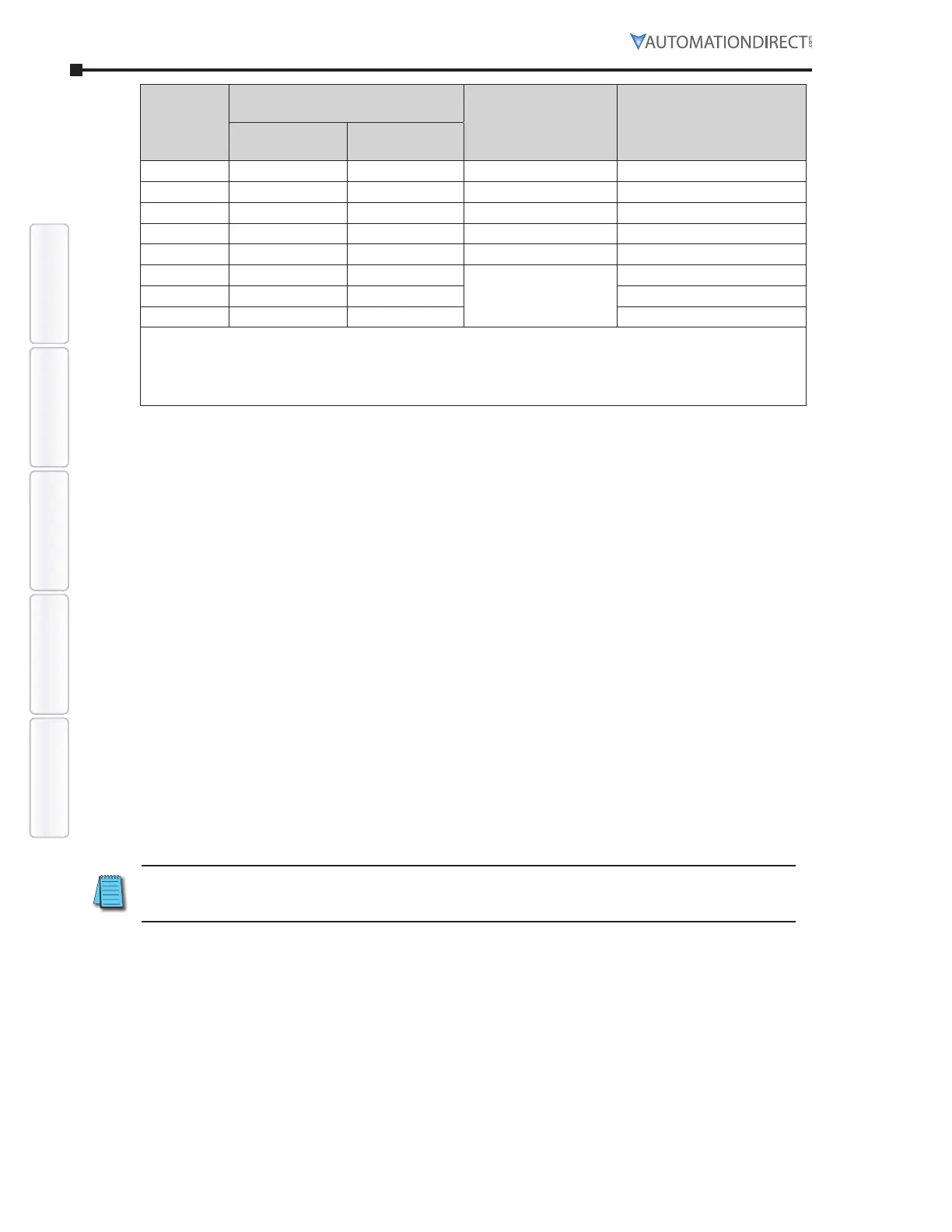
Monitoring DI/DO Codes ParametersAlarms Wiring
400W 100 10 5 60
750W 100 28 14 60
1500W 100 28 14 30
2000W 30 40 20 15
3000W
20 40 20 15
5500W** 20 0
See calculations below
for recommended value
10
7500W** 20 0 10
15000W** 20 0 5
* Using a resistance value lower than the minimum specified can cause too high of a current
draw for the drive to handle. Note that there is no maximum resistance limit.
** 5.5 kW, 7.5 kW, and 15kW drives do not have an internal resistor. Enter your external
resistance and wattage values here.
When the regenerative energy exceeds the capacity of built-in regenerative resistor, you should
use an external regenerative resistor. Please pay special attention to the following when using
an external regenerative resistor.
•
Please choose the correct resistance (P1�052) and wattage (P1�053) for the regenerative
resistor; otherwise it might influence the performance� For drives up to and including 3kW,
the drives include a built-in resistor� For heat dissipation reasons the Wattage of the actual
resistor is decreased in P1�053 vs� what is actually printed on the resistor� If the resistor was
externally mounted with good airflow then the full Watt value of the resistor can be entered
in P1�053� For further drive and resistor protection the drive's firmware uses half that value
(P1�053/2) for energy regeneration calculations�
•
When using an external regenerative resistor, please note that its resistance must be greater
than the resistance of the built-in regenerative resistor� For general application, you can
connect more than one resistor in series� If the value (from resistors connected in series)
exceeds the rated range, you can reduce the value by connecting the resistor in parallel� If you
want to connect the resistors in parallel to increase the power of the regenerative resistor,
please make sure the wattage and resistance capacity meet the requirements�
See the following diagram and settings for connecting the regenerative resistors in serial and
parallel�
This simplified diagram of the braking resistor circuitry shows the connections and usage
of the internal regen resistor and factory-installed P3-D jumper (pre-installed on ≤ 3kW
drives), and how the optional external resistor is used� External resistors are recommended
(disconnect the P3-D jumper) in regen applications to remove heat from the drive that would
be generated by using the internal regen resistor�
Note: If the internal AND an external resistor are both used (the P3-D jumper is NOT
removed), make sure that the parallel resistance is still within the specified range for the
drive in the table above).