Chapter 2: Installation
Page 2–11SureServo2 User Manual – 1st Edition – 05/20/2021
Parameters DI/DO Codes MonitoringWiring Alarms
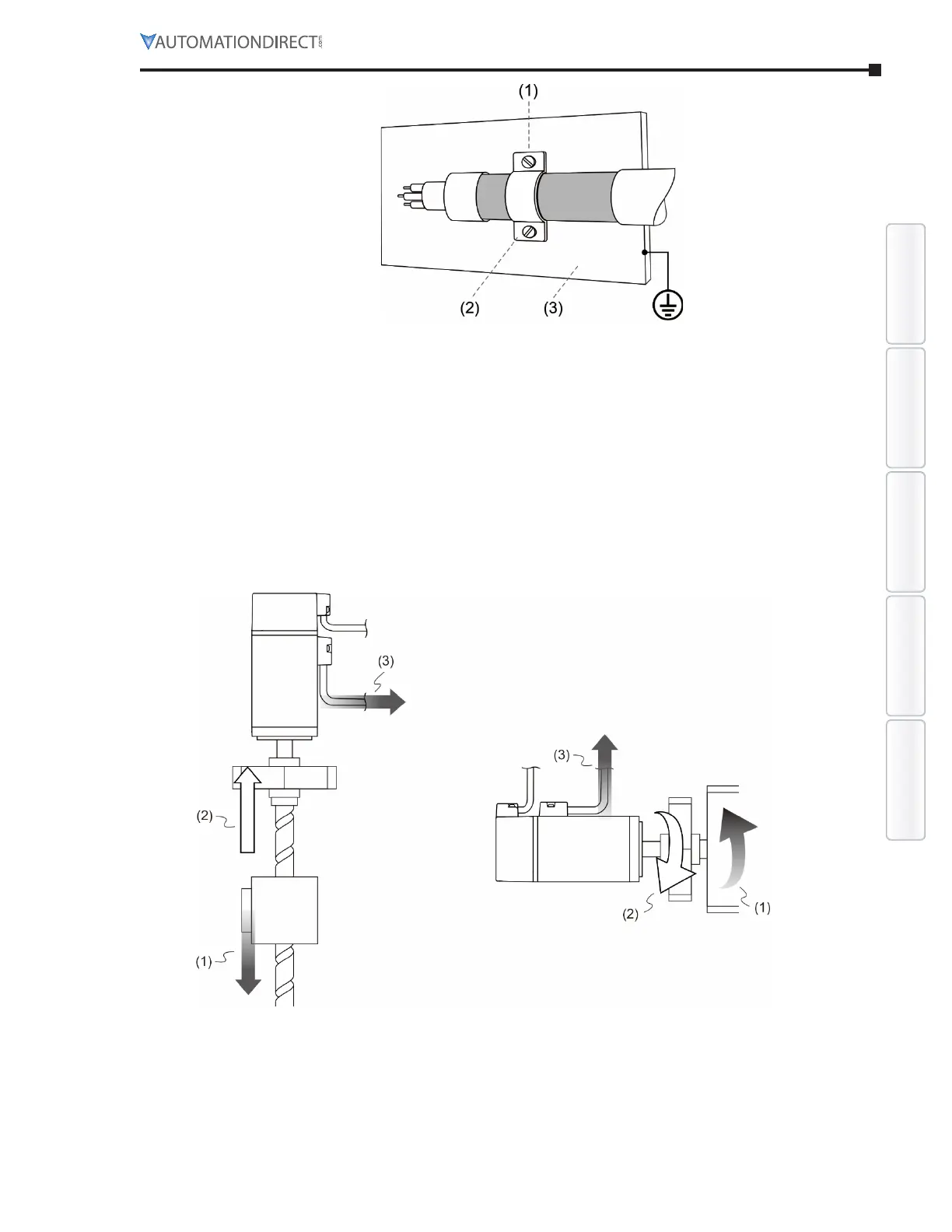
1) Any protective paint of the U-shape saddle EMC cable clamp and metal plate should be
removed in order to ensure good contact.
2) EMC cable clamp U-shape saddle
3) Well-grounded metal plate
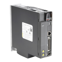
When the direction of torque is different from the direction of rotation, the energy generated
returns to the servo drive from the load. This energy is turned into electricity in the capacitor
bank of the DC Bus and thus increases the voltage. When the voltage reaches a given value,
it is consumed by a regenerative resistor. Servo drives up to 3kW have a built-in regenerative
resistor. You can also use the external regenerative resistor if needed. See the table on the
following page for allowable external braking resistor values.
1) Moving direction of the object
2) Direction of torque
3) Regenerative energy
The built-in regenerative resistor in the SureServo2 is as follows: