B-35
(A)
Photo
electric
sensor
(B)
Fiber
optic
sensor
(C)
Door/Area
sensor
(D)
Proximity
sensor
(E)
Pressure
sensor
(F)
Rotary
encoder
(G)
Connector/
Socket
(H)
Temp.
controller
(I)
SSR/
Power
controller
(J)
Counter
(K)
Timer
(L)
Panel
meter
(M)
Tacho/
Speed/ Pulse
meter
(N)
Display
unit
(O)
Sensor
controller
(P)
Switching
mode power
supply
(Q)
Stepper
motor&
Driver&Controller
(R)
Graphic/
Logic
panel
(S)
Field
network
device
(T)
Software
(U)
Other
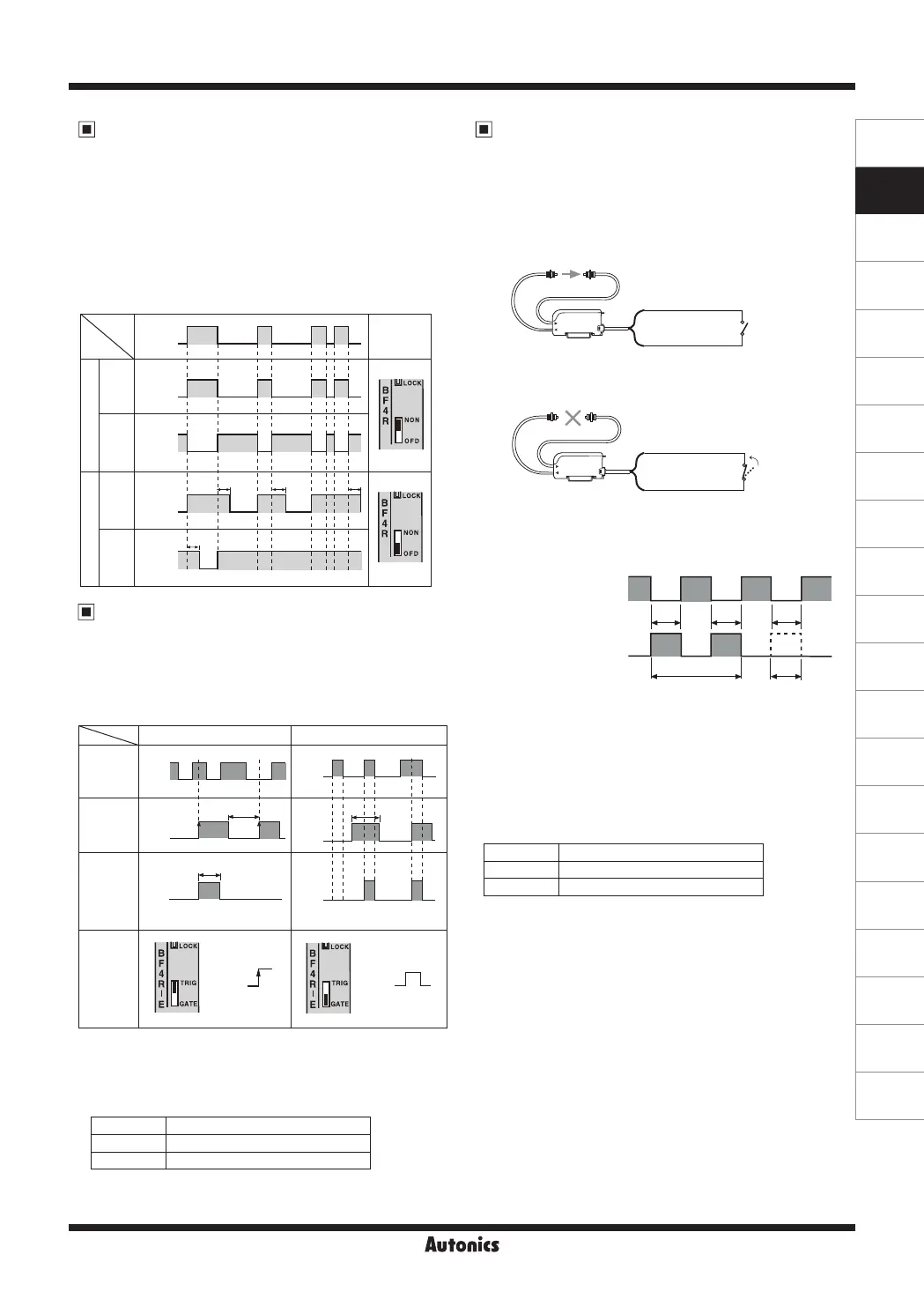
Fiber Optic Amplier
Standard type and Remote sensitivity setting type both
contain a built-in approx. 40ms fixed OFF Delay timer. The
timer works when the timer selection switch is set to 'OFD'.
The output is turned off after remaining on for additional
40ms at OFF position of the sensing output. It is useful
when the response time of the connected device is slow or
when the sensing signal from a tiny object is too short.
External synchronization input
function [BF4R(G)-E]
By using external synchronization function, the time
for making sensing can be specified by external
synchronization. Trigger synchronization and gate
synchronization are available.
State Signal condition
High 4.5-30VDC or Open
Low 0-1VDC
State Signal condition
High 4.5-30VDC or Open
Low 0-1VDC
OFF Delay timer function
(BF4R/BF4RP/BF4R-R/BF4G/BF4GP/BF4G-R)
Stop transmission function
[BF4R(G)-E]-Operation test
● Below test is available under Light ON state only.
● If input of stop transmission is at Low state, transmission
light will be stopped.
● It can check normal or abnormal state of the sensor
without moving the target.
<Input signal condition for External synchronization>
<Input signal condition for Stop transmission>
※
T≥0.5ms
(using interference prevention function: T≥0.7ms)
※
(Note) Actual signal detected by sensor.
※
①
: Transmission area,
②
: Stop transmission area
※
(Note1) If transmission is stopped control output must
turn on, but if control output does not turn on,
it seems that sensor has some problems.
※
T≥0
.5ms
(When using interference prevention function T≥0.7ms)
[If input of stop transmission is at High or Open state,
light is transmitted.]
[If input of stop transmission is at Low, light is transmitted.]
High
(OFF)
Low
(ON)
Input of stop
transmission
Sensing output
(If it is in ON
state when light
is not received)
T T T
① ① ①①
② ② ②
Normal
Abnormal
(Note1)
ON
OFF
※
Control output is fixed
as 40ms.
Trigger synchronization Gate synchronization
(Note)
Sensing
signal
External
synchroni-
zation
input
Control
output
External
synchroni-
zation
selection
switch
Approx. 40ms
High
Low
High
Low
ON
OFF
ON
OFF
ON
OFF
ON
OFF
T T
GATE
TRIG
Timer
selection
switch
Light
ON
Dark
ON
Light
ON
Dark
ON
ON
OFF
ON
OFF
ON
OFF
ON
OFF
T T T
T
Sensing
Non-
Sensing
<Time Chart>
T
≒
40
㎳
Sensing
state
Output
operation
Normal
Timer
(Orange)Input of stop transmission
(Blue)0V
High or
Open
(Orange)Input of stop transmission
(Blue)0V
Low
 Loading...