J-36
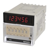
FXY Series
Specications
Features
DIN W72×H36mm Of Counter/Timer With Indication Only
Model
Please read “Safety Considerations” in operation
manual before using.
Model Indicator
FX4Y-I2 FX4Y-I4 FX6Y-I2 FX6Y-I4
Display digit 4-digit 6-digit
Character size (W×H) 8×14mm 4×8mm
Power supply
24VAC~ 50/60Hz,
24-48VDC
З
100-240VAC~ 50/60Hz
24VAC~ 50/60Hz,
24-48VDC
З
100-240VAC~ 50/60Hz
Permissible voltage range 90 to 110% of rated voltage
Power consumption
Max. 2.8VA
(24VAC~ 50/60Hz),
Max. 1.8W (24-48VDC
З
)
Max. 3.8VA
(240VAC~ 50/60Hz)
Max. 2.8VA
(24VAC~ 50/60Hz),
Max. 1.8W (24-48VDC
З
)
Max. 3.8VA
(240VAC~ 50/60Hz)
Max. counting speed of CP1/CP2 Selectable 1cps/30cps/2kcps/5kcps (DIP switch)
Return time Max. 500ms
Min. signal width INHIBIT, RESET: approx. 20ms
Input method
Selectable voltage input (PNP) method or no-voltage input (NPN) method
[Voltage input (PNP) method]-input impedance: max. 10.8kΩ, [H]: 5-30VDC
З
, [L]:0-2VDC
[No-voltage input (NPN) method]-short-circuit impedance: max. 470Ω, short-circuit residual voltage: max. 1VDC,
open-circuit impedance: min. 100kΩ
Repeat/Set/Voltage/Temp. error Max. ±0.01% ±0.05 sec
Insulation resistance Over 100MΩ (at 500VDC megger)
External power supply Max. 12VDC
З
±10% 50mA
Memory retention Approx. 10 years (non-volatile memory)
Dielectric strength 2,000VAC 50/60Hz for 1 min (between all terminals and case)
Noise
immunity
AC voltage ±2kV the square wave noise (pulse width 1μs) by noise simulator
AC/DC voltage ±500V the square wave noise (pulse width 1μs) by noise simulator
Vibration
Mechanical 0.75mm amplitude at frequency 10 to 55Hz (for 1 min) in each X, Y, Z direction for 1 hour
Malfunction 0.5mm amplitude at frequency 10 to 55Hz (for 1 min) in each X, Y, Z direction for 10 minutes
Shock
Mechanical 300m/s
2
(approx. 30G) in each X, Y, Z direction for 3 times
Malfunction 100m/s
2
(approx. 10G) in each X, Y, Z direction for 3 times
Environment
Ambient temp. -10 to 55
℃
, storage: -25 to 65
℃
Ambient humi. 35 to 85%RH, storage: 35 to 85%RH
Protection structure IP40 (front part, IEC standard)
Approval
Weight
※
1
Approx. 175g (approx. 120g)
※
1: The weight includes packaging. The weight in parenthesis is for unit only.
※
Environment resistance is rated at no freezing or condensation.
● Counting speed: 1cps/30cps/2kcps/5kcps
● Selectable voltage input (PNP) method or
no-voltage input (NPN) method
● Input mode: Up, Down, Up/Down
● Dot for Decimal Point / Hour. Min. Second by RESET key
● Wide range of input power supply
: 100-240VAC 50/60Hz,
24VAC 50/60Hz, 24-48VDC universal
● Selectable Counter or Timer function by internal DIP switch
● Changed case color (ivory → black)
● [Counter]
20 input modes
● [Timer]
Various time setting range-6-digit model: 0.01 sec to 99999.9 hour /
4-digit model: 0.01 sec to 9999 hour
● Output: Indicator
Model Display digit Size Output Power supply
FX4Y-I2
9999 (4-digit)
DIN W72×H36mm Indicator
24VAC 50/60Hz, 24-48VDC
FX4Y-I4 100-240VAC 50/60Hz
FX6Y-I2
999999 (6-digit)
24VAC 50/60Hz, 24-48VDC
FX6Y-I4 100-240VAC 50/60Hz