SV setting Parameter group 1 Parameter group 2
+
3 sec
RUN mode
3 sec
3 sec
3 sec
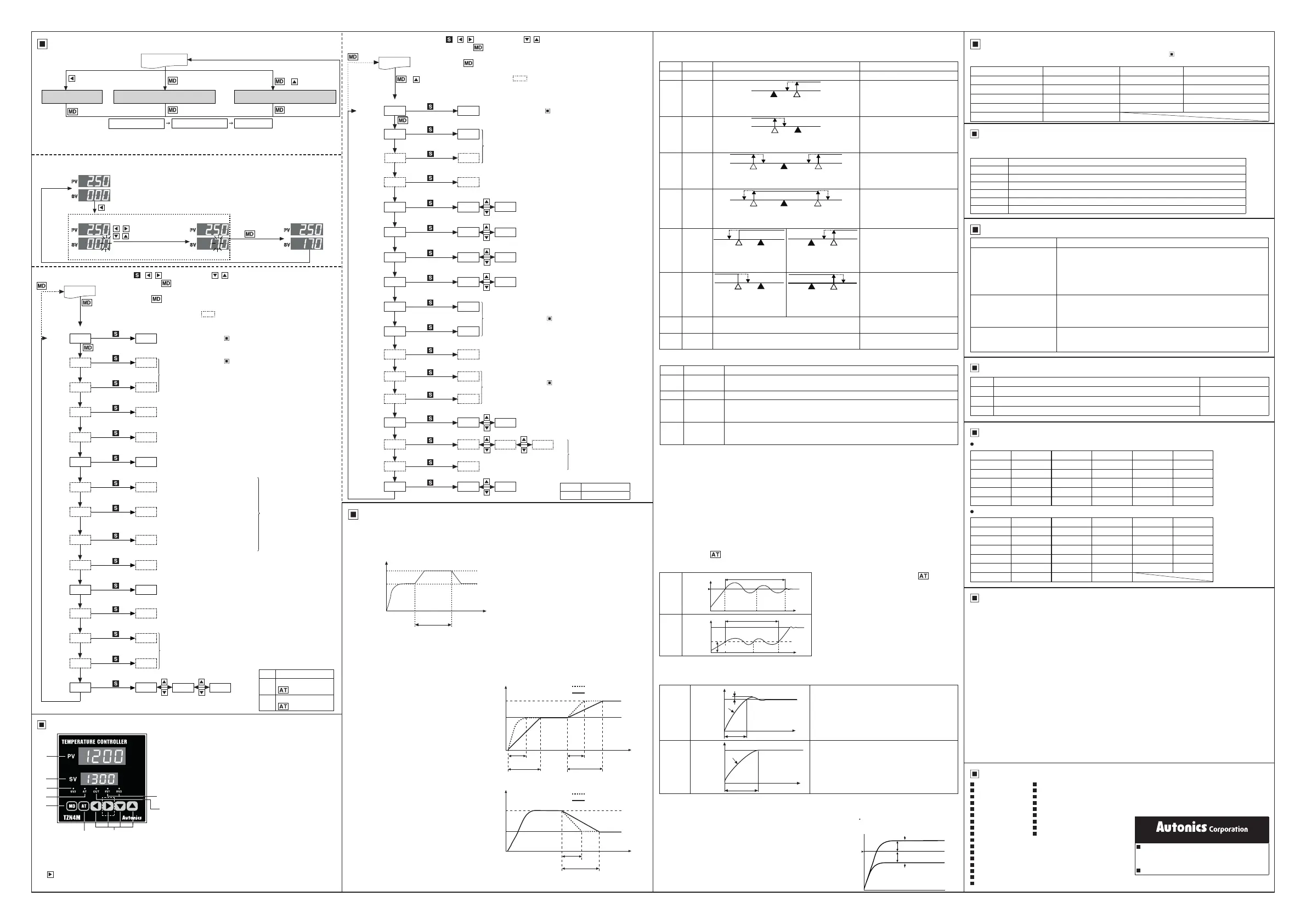
7. Mode key
:enterparametergroup,returntoRUNmode,switchparameters,savesettingvalues
8. Auto-tuning key
: hold the key for 3 seconds to start auto-tuning. Hold the key for 5 seconds while auto-
tuning to stop auto-tuning.
9. Setting keys
:enterSVchangemode,switchelds,changevalue
( keyinthedottedlineisonlyavailableinTZN4MandTZN4Lmodels)
1. Present value (PV) display (red)
:
RUNmode:displaysthecurrentvalue(PV)
Setting mode: displays parameters
2. Set value (SV) display (green)
:
RUNmode:displaysthesetvalue(SV)
Setting mode: displays parameter setting values
3. SV2 operation indicator
: turns ON when SV2 is operating
4. Auto-tuning indicator
: turns ON when auto-tuning
5. Control output operation indicator
: turns ON when
control output is ON. Does not operate when the input
type is current output.
6. Event output indicator
: turns ON when the according
event output is ON.
( )key:Switchelds
, key: Change values
key
key
①
RUN mode
②
SV setting mode
8 9
1
3
2
5
6
4
7
Parameter groups
※
Parametersettingorder
Parameter group 2
Parameter group 1 SV setting
Theparametersarerelatedtoeachother.Pleasesettheparametersintheorderabove.
※
Whenthereisnokeyinputfor60secondswhileinSVsettingmodeorparametergroups,theunitwillreturn
to RUN mode automatically.
● SV setting
※
When changing the previous SV of 0
℃
to 170
℃
,
Thesettingeldwillblink.
③
Complete SV setting
Unit Description
1. SV2 temperature
YoucancontrolanadditionaltemperaturevalueatadesiredrangebyusingSV2.Connectacontactsignal(under
5VDC,250
㎂
)attheexternalterminal,tooperateintherangewherethesignalturnsON.
Set the SV2 temperature in SV2 temperature [
SU-2
] in parameter group 1.
SV
SV 2 [
SU-2
]
External terminal
(SV2IN)
ON
Temperature
Time
E.g.)Theinternaltemperatureofanelectricovenmay
drop rapidly if the door is opened while the oven
ismaintainingaspecictemperature.SetSV2
temperature [
SU-2
]toahighervaluethanSV,and
inputasignaltotheexternalterminal(SV2IN),to
quickly raise the temperature.
2. Ramp
Therampfunctioncandelaytherateoftemperaturerise/fall.IftheSVvalueischangedduringstabilizedcontrol,
the temperature of the controlled target will rise/fall during ramp up/down time [
RAPU
,
RAPD
] of parameter group
1. The ramp function activates when the power is reset or when the SV value is changed during stable control.
※
The ramp up/down time [
RAPU
,
RAPD
] appear only when the ramp function [
RAMP
] of parameter group 2 is
set to
ON
.
●Rampuptime[
RAPU
]
When delaying the rise of initial control
temperature or changing the SV during
stablecontrol,youcandelaytemperature
rise. Set the ramp up time [
RAPU
] longer
thanthetemperaturerisetime(tu)when
not using the ramp function.
: Not using ramp function
: Using ramp function
Changed SV
Initial SV
Time
tu tu
Ramp up time
[
RAPU
]
Ramp up time
[
RAPU
]
Temperature
●Rampdowntime[
RAPD
]
Delays declining temperature. Set the
ramp down time [
RAPD
] longer than the
temperaturedeclinetime(td)whennot
using the ramp function.
: Not using ramp function
: Using ramp function
Changed SV
Initial SV
td
Time
Ramp down time
[
RAPD
]
Temperature
Functions
Com.
speed
Cautions during Use
Major Products
RS485 Communication
ApplicableformodelsthatsupportRS485communication.Pleasereferto' Ordering Information'.
It is used to transmit PVorSV,and/orsettheSV.
Protocol BCC Communication speed 2400,4800,9600bps
Applied standard EIA RS485 Start bit 1-bitxed
Max. connections 31units(address:1to99) Data bit 8-bitxed
Communication method 2-wire half duplex Paritybit None
Synchronization method Asynchronous Stop bit 1-bitxed
Communication distance Within 1.2km
Error Dispaly
Display Description Troubleshooting
OPEN
Blinks when input is disconnected. Check input status.
HHHH
Blinks when the measured input value is higher than the temperature range.
Adjust the value to within
the temperature range.
LLLL
Blinks when the measured input value is lower than the temperature range.
Symptoms Troubleshooting
OPEN
isdisplayedonthePV
display during operation
Disconnect the power and check the input connection.
Iftheinputisconnected,disconnecttheinputwiringfromthetemperature
controllerandshortthe+and-terminals.Powerthetemperaturecontroller
and check if it displays the room temperature. If it does not display the room
temperature and continues to display
OPEN
,thecontrollerisbroken.Please
contactourtechnicalsupport.(Inputtypeisthermocouple)
Load(heater,etc.)doesnot
operate
during operation
Check the state of the control output indicator on the front panel.
Iftheindicatorisnotworking,checkparametersettings.Iftheindicatoris
working,disconnectthewiringfromtheoutputterminalofthetemperature
controllerandchecktheoutput(replaycontact,SSRdrive,current)
ERR0
(error)isdisplayedon
thePVdisplayduringoperation
Indicatesdamagetointernalchipbystrongnoise(2kVAC).
Pleasecontactourtechnicalsupport.Locatethesourceofthenoiseand
devise countermeasures.
Troubleshooting
Parameter group 2
Parameter Default Parameter Default Parameter Default
SU-2 0 P #0 IN-B 0
AL1 10 I 0 REST )0
AL2 10 D 0 RAPU 10
LBA 600 T 20 RAPD 10
AHYS 2 HYS 2 LOC OFF
Parameter Default Parameter Default Parameter Default
IN-T KCaH O-FT HEAT FS-L `00
EU-1 AL-1 UNIT ?C RAMP OFF
EU-2 AL-2 H-SC 1300 BPS 2400
AL-T AL-A L-SC `00 ADRS 01
AtT TVN1 DOT 0 LOC OFF
PIDT PIdS FS-H 1300
Parameter group 1
Factory Default
4. Auto-tuning
Auto-tuning allows the temperature controller to detect the thermal characteristics and response rates of the
controltarget.ItthencalculatesthePIDtimeconstantandsetsthevaluetoallowfastresponseratesandhigh
accuracy. Hold the key for 3 seconds during RUN mode to start auto-tuning. The auto-tuning indicator will
blink.Whenauto-tuningiscompleted,theauto-tuningindicatorwilldurnoffandthePIDtimeconstantwillbe
saved to each parameter of parameter group 1. The saved parameters can be adjusted as desired.
Tomanuallystopauto-tuning,holdthe key for 5
seconds.Whenauto-tuningisstopped,thecontroller
maintainsthePIDvaluebeforeauto-tuning.
TZN Series supports 2 auto-tuning modes.
Select TUN1 mode or TUN2 mode [
TUN1
,
TUN2
]
from auto-tuning mode [
AtT
] of parameter group 2.
※
Run auto-tuning during initial setup of the
temperature controller.
※
If the thermal characteristics of the control target
devicehaschangedafterextendedusage,re-run
auto-tuning.
3. Alarm (Event)
Alarmoutputcanbeconguredbycombiningalarmoperationandalarmoptions.Setthealarmoperationin
event 1/2 [
EU1
,
EU2
]ofparametergroup2,andsetthealarmoptionsinalarmoption[
AL-T
].
1)Alarmoperation
Mode Name Alarm operation Description
ㅁAL-0
- - Alarm output not used.
AL-1
Deviation
high-limit
alarm
SV
100℃
PV
110℃
OFF ONH
IfthedeviationofPVandSVare
higherthanthehigh-limitdeviation,
the alarm output turns ON.
High-limit deviation: 10℃
AL-2
Deviation
low-limit
alarm
PV
90℃
SV
100℃
OFFON H
IfthedeviationofPVandSVare
higherthanthelow-limitdeviation,
the alarm output turns ON.
Low-limit deviation: 10℃
AL-3
Deviation
high-limit
/low-limit
alarm
PV
90℃
PV
110℃
SV
100℃
OFFON ONH H
IfthedeviationofPVandSVare
higher than the high-limit deviation
orlow-limitdeviation,thealarm
output turns ON.
High-limit/low-limit deviation: 10℃
AL-4
Deviation
high-limit
/low-limit
reverse
alarm
PV
90℃
PV
110℃
SV
100℃
OFF OFFONH H
IfthedeviationofPVandSVare
higher than the high-limit deviation
orlow-limitdeviation,thealarm
output turns OFF.
High-limit/low-limit deviation: 10℃
AL-5
Absolute
value
high-limit
alarm
PV
90℃
SV
100℃
OFF ONH
SV
100℃
PV
110℃
OFF ONH
AlarmoutputturnsONwhenPVis
higher than the absolute value.
Absolute value alarm:
90℃
Absolute value alarm:
110℃
AL-6
Absolute
value
low-limit
alarm
PV
90℃
SV
100℃
OFFON H
SV
100℃
PV
110℃
OFFON H
AlarmoutputturnsONwhenPVis
lower than the absolute value.
Absolute value alarm:
90℃
Absolute value alarm:
110℃
SBA
Sensor
break
-
Alarm output turns ON when sensor
disconnection is detected.
LBA
Loop
break
-
Alarm output turns ON when loop
break is detected.
※
H: Alarm output hysteresis [
AHYS
]
Mode Name Description
AL-A
Standard
alarm
AlarmoutputturnsONuponalarmcondition,andalarmoutputturnsOFFwhen
condition is cleared.
AL-B
Alarm latch Alarm output turns ON and maintains ON upon alarm condition.
AL-C
Standby
sequence
Therstalarmconditionisignored.Itwilloperateasstandardalarmfromthesecond
alarmcondition.Ifitisunderalarmconditionwhenpowerissupplied,itwillignorethe
condition and operate as standard alarm from the next alarm condition.
AL-D
Alarm latch
and standby
sequence
It will operate as both alarm latch and standby sequence upon alarm condition. If it is
underalarmconditionwhenpowerissupplied,itwillignoretheconditionandoperate
as alarm latch from the next alarm condition.
3)Sensorbreakalarm
Alarm output turns ON when sensor is not connected or loses its connection during temperature control. Sensor
disconnection can be tested by connecting buzzers or other devices to the alarm output contact. Sensor break
alarm output operates through EV1 OUT or EV2 OUT contacts. Alarm output is disengaged after resetting the
power.
4)LoopbreakAlarm(LBA)
Diagnose control loop and transmit alarm output through temperature change of control target. During
heating(cooling)control,thealarmoutputturnsONifthePVdoesnotrise/dropbyaspecicamount(approx.2℃)
during LBA monitoring period [
LBA
]whilecontroloutputamountisat100%(0%).
※
Ifthethermalresponseofthecontroltargetisslow,theLBAmonitoringperiod[
LBA
] of parameter group 1
should be set longer.
※
LBAonlyoperateswhenthecontroloutputamountis100%(0%)soitcannotbeusedincurrentoutputmodels.
※
IfthealarmoutputturnsONafterthesensorhasbeendisconnected,thealarmoutputwillnotturnOFFeven
afterreconnectingthesensor.Todisengagethealarmoutput,thetemperaturecontrollerpowermustbereset.
TUN1
mode
[
TUN1
]
Temperature
Time
SV
Auto-tuning
TUN2
mode
[
TUN2
]
Temperature
Time
70%
SV
Auto-tuning
6. Input correction [
IN-B
]
Used to correct deviation from external devices such as temperature controllers.
E.g.)Iftheactualtemperatureis80
℃
but the display value is 78
℃
,settheinputcorrection[
IN-B
] value to
2
and it will display 80
℃
as the display value.
High-
speed
response
mode
[
PIdF
]
Temperature
Time
SV
S
t
PV
Usedtominimizethetime(t)requiredtoreachtheSV.
Overshoot(S)occurs.
Used in machinery that may require warming up.
(injectionmoldingmachine,electricfurnace,etc.)
Low-
speed
response
[
PIdS
]
Temperature
Time
t
SV
PV
Usedtominimizeovershoot(S).Time(t)requiredto
reach SV may be slower.
Used for machinery or environments where overshoot
maycauseexplosionorre.(oiltemperaturecontrol,
metalplatingmachinery,etc.)
5. Dual PID control
TheresponserateofthePIDcontrolcanbeselecteddependingonthecharacteristicsofthecontroltarget.
Select high-speed response mode or low-speed response mode [
PIdF
,
PIdS
]fromPIDmethod[
PIDT
] of
parameter group 2.
PhotoelectricSensors Temperature Controllers
Fiber Optic Sensors Temperature/Humidity Transducers
Door Sensors SSRs/PowerControllers
Door Side Sensors Counters
Area Sensors Timers
ProximitySensors PanelMeters
PressureSensors Tachometer/Pulse(Rate)Meters
Rotary Encoders Display Units
Connector/Sockets Sensor Controllers
SwitchingModePowerSupplies
Control Switches/Lamps/Buzzers
I/O Terminal Blocks & Cables
Stepper Motors/Drivers/Motion Controllers
Graphic/LogicPanels
Field Network Devices
LaserMarkingSystem(Fiber,CO
₂
,Nd:YAG)
Laser Welding/Cutting System
http://www.autonics.com
HEADQUARTERS:
18,Bansong-ro513beon-gil,Haeundae-gu,Busan,
SouthKorea,48002
TEL: 82-51-519-3232
E-mail:
sales@autonics.com
DRW170714AA
7. Manual reset [
REST
]
Whenusingproportionalcontrol(Pcontrol),thetimeoftemperature
rising time and falling time may differ depending on factors such as
the heat capacity of the control device or the heater. A certain amount
of deviation occurs even under stable conditions.
Thisdeviationisreferredtoasoffset,andcanbecongured/corrected
using manual reset [
REST
].
WhenPVandSVareequal,theresetvalueis50.0%.IfthePVis
lowerthantheSVduringstablecontrol,setthevaluetoover50.0%,
andifthePVishigherthantheSV,setthevaluetounder50.0%
Conguringmanualreset[
REST
]
according to control results.
Reset value set at under 50.0%
Reset value set at over 50.0%
Offset
Offset
SV
1.Followinstructionsin'CautionsduringUse'.Otherwise,Itmaycauseunexpectedaccidents.
2. Check the polarity of the terminals before wiring the temperature sensor.
ForRTDtemperaturesensor,wireitas3-wiretype,usingcablesinsamethicknessandlength.
Forthermocouple(CT)temperaturesensor,usethedesignatedcompensationwireforextendingwire.
3. Keep away from high voltage lines or power lines to prevent inductive noise.
Incaseinstallingpowerlineandinputsignallineclosely,uselinelterorvaristoratpowerlineandshielded
wire at input signal line.
Do not use near the equipment which generates strong magnetic force or high frequency noise.
4. Install a power switch or circuit breaker in the easily accessible place for supplying or disconnecting the
power.
5.Donotusetheunitforotherpurpose(e.g.voltmeter,ammeter),buttemperaturecontroller.
6.Whenchangingtheinputsensor,turnoffthepowerrstbeforechanging.
Afterchangingtheinputsensor,specifyinternalswitchandmodifythevalueofthecorrespondingparameter.
7. Do not overlapping communication line and power line.
Use twisted pair wire for communication line and connect ferrite bead at each end of line to reduce the effect
of external noise.
8. Make a required space around the unit for radiation of heat.
Foraccuratetemperaturemeasurement,warmuptheunitover20minafterturningonthepower.
9. Make sure that power supply voltage reaches to the rated voltage within 2 sec after supplying power.
10. Do not wire to terminals which are not used.
11. This unit may be used in the following environments.
①
Indoors(intheenvironmentconditionratedin'Specications')
②
Altitudemax.2,000m
③
Pollutiondegree2
④
Installation category II
Comprehensive Device Management Program[DAQMaster]
DAQMaster is a comprehensive device management software for setting parameters and monitoring
processes. DAQMaster can be downloaded from our website at www.autonics.com.
Item Minimumspecications
System IBMPCcompatiblecomputerwithPentium
Ⅲ
or above
Operations Windows98/NT/XP/Vista/7/8/10
Memory 256MB+
Hard disk 1GB+ of available hard disk space
VGA Resolution: 1024×768 or higher
Others RS232Cserialport(9-pin),USBport
2)Alarmoptions
ON ON1
OFF
Unlock
ON
Lock parameter 1
( keyavailable)
ON1
Lock parameter 1
( keyunavailable)
Setting range:
※
1: : ( )key-Switchelds, , key-Change values
※
2:Pressthe key after checking or changing the values in parameter
settings to save the setting value and move to the next parameter.
※
Hold the key for 3 seconds anytime during parameter settings to save the
setting value and return to RUN mode.
※
The dotted line parameters may not appear depending on the model or
other parameter settings.
SV 2
temperature
Event 1
alarm
temp.
Event 2
alarm
temp.
LBA
monitoring
time
Alarm
output
hysteresis
Proportional
band
Integral
time
Derivative
time
Control
period
Hysteresis
Input
correction
Manual
reset
Ramp
up time
Ramp
down time
Lock
SU-2
AL1
AL2
LBA
AHYS
P
I
D
T
HYS
IN-B
REST
RAPU
RAPD
LOC
3 sec
3 sec
RUN mode
0
10
10
600
2
#0
0
0
20
2
0
)0
10
10
OFF
● Parameter group 1
※
2
Setting range: refer to " Input Type and Range".
Setting range: refer to " Input Type and Range".
※
[
AL1
,
AL2
] parameters do not appear when Event 1/2 [
EU-1
,
EU-2
] of parameter group 2 is set to
AL-0
,
LBA
,
SBA
.
※
[
AL2
] parameter only appears in models that support Event 2
output.
Setting range: 0 to 999 sec
※
Only appears when Event1/2 [
EU-1
,
EU-2
] of parameter
group 2 is set to
LBA
.
※
Does not appears in current output models.
Setting range: 1 to 100
℃
/
℉
(0.1to100.0
℃
/
℉
)
※
Does not appears when Event 1/2 [
EU-1
,
EU-2
] of parameter
group 2 is set to
AL-0
,
LBA
,
SBA
.
Setting range: 0.0 to 100.0%
※
ON/OFF control: Set to
)0
,PIDcontrol:Settoover
)0
※
OnlyappearsduringPID
control(proportionalband
[
P
] set to over
)0
).
Setting range: 1 to 100
℃
/
℉
(0.1to100.0
℃
/
℉
)
※
OnlyappearsduringON/OFFcontrol(proportionalband
[
P
] set to
)0
).
Setting range: -49 to 50
℃
/
℉
(-50.0to50.0
℃
/
℉
)
Setting range: 0.0 to 100%
※
OnlyappearswhenPcontrol(proportionalband[
P
] set to over
)0
,integraltime[
I
],andderivativetime[
D
] are set to
0
)
Setting range: 1 to 99 min
※
Only appears when ramp function [
RAMP
] of parameter group
2 is set to
ON
.
Settingrange:0to3,600sec
※
Integral operation is turned OFF
when set to
0
.
Settingrange:0to3,600sec
※
Derivative operation is turned
OFF when set to
0
.
Setting range: 1 to 120 sec
※
Set to a small value in SSR drive
outputmodels.(i.e.2sec)
PV display SV display
※
1
● Parameter group 2
+
3 sec
Setting range: refer to " Input Type and Range".
OFF
Unlock
ON
Lock parameter 2
Setting range:
Input type
Event 1
Event 2
Alarm
option
Auto-tuning
mode
PIDmethod
Heating/
Cooling
Temperature
unit
SV
high-limit
SV
low-limit
Decimal
point
Trans. output
high-limit
Trans. output
low-limit
Ramp
function
3 sec
RUN mode
※
2
Setting range: refer to " Input Type and Range".
Setting range: refer to '3. Alarm'.
※
Event 2 [
EU-2
] only appears in models that support Event
2 output.
Setting range: refer to '3. Alarm'.
※
Does not appear when Event 1/2 [
EU-1
,
EU-2
] is set to
AL-0
,
LBA
,
SBA
.
Setting range:
0
,
)0
,
)00
,
)000
※
Only appears with analog input.
Setting range: refer to " Input Type and Range".
※
OnlyappearsinmodelsthatsupportPVtransmission.
※
1
Com.
address
Lock
※
Only appears in models
that support RS485
communication
Settingrange:1to99(address)
※
1: : ( )key-Switchelds, , key-Change values
※
2:Pressthe key after checking or changing the values in parameter
settings to save the setting value and move to the next parameter.
※
Hold the key for 3 seconds anytime during parameter settings to save the
setting value and return to RUN mode.
※
The dotted line parameters may not appear depending on the model or
other parameter settings.
※
Pleasesetaccordingtocontrolapplication.
Do not change the settings during operation.
Itmayresultinreoraccidents.
PV display
SV display
IN-T
EU-1
EU-2
AL-T
AtT
PIDT
O-FT
UNIT
H-SC
L-SC
DOT
FS-H
FS-L
RAMP
KCaH
AL-1
AL-2
AL-A
1300
`00
0
1300
`00
※
2
※
1
ON
ON
4800 9600
BPS
ㅁㅁ ADRS
LOC
01
OFF
OFF
2400
TVN2
PIdF
COOL
?F
TVN1
PIdS
HEAT
?C

 Loading...