4
DRILL ¼” (6mm) DRILL ¼” (6mm)
TOP
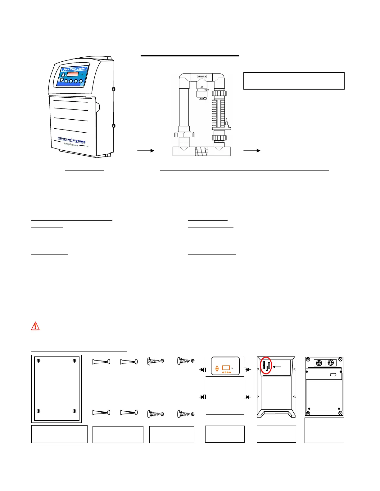
TEMPLATE FOR DRILLING
POOL PILOT SOFT TOUCH
& POOL PILOT DIGITAL
MOUNTING HOLES.
DRILL 4 ¼” (6mm) HOLES FOR
WALL ANCHORS WHERE SHOWN.
P/N 18550
BOTTOM
DRILL ¼” (6mm) DRILL ¼” (6mm)
Place Template on
mounting location. Level,
mark holes and drill.
Loosen four
fastening screws
Disconnect (4)
wire harness.
Mount the Control
Box and tighten
the (4) mounting
screws.
POOL PILOT
Use the (4) provided
plastic anchors and
insert into drilled holes.
Attach the (4)
provided screws,
Section 2a – INSTALLATION
Main Components
Control Box Patented Automatic Flow Bypass Manifold Assembly
converts incoming AC power to a Low ELECTROLYTIC SUPERCELL TRI-SENSOR ASSEMBLY
Voltage DC current, which energizes the receives Low Voltage DC current from ensures that adequate Flow,
Cell(s). the Power Circuit Board, which initiates Salt Level, and Water
the electrolytic process. Temperatures are satisfactory to
prevent abusive conditions for the
cell to operate.
SPECIFICATION RATINGS: Maximum daily
Input Power: 115 VAC (3.0 AC amps) Cl
2
Output Rating: SC-60 1.92 lbs/day (0.88 kg/day)
230 VAC (1.5 AC amps) @ Cell Power 3 SC-48 1.56 lbs/day (0.71 kg/day)
50/60 Hz (8 amps DC) SC-36 1.28 lbs/day (0.58 kg/day)
Output Power: Cell Power 1 (5.0* DC amps) Agency Approvals: NSF, ETL
US
, ETL
C
, CE
Cell Power 2 (6.5* DC amps)
Cell Power 3 (8.0* DC amps) Internal Pump Relay is rated for 30-amp max.
*Indicates nominal amperage output. The dual axis controller will slightly vary the amps to optimize the power to the cell.
12’ (3.6 m) of Cell and Tri-Sensor cords are provided with the unit. Ensure that the manifold is located within that distance
from the control box with enough slack to allow for removal for service or maintenance.
The Digital display provides full information and diagnostics for maintenance and operation of your system. The
programmable settings are retained on a microprocessor chip with the clock setting backed-up with a CR-2025 lithium battery.
CAUTION: To avoid over-saturation conditions of your spa, it is suggested to locate the cell downstream of all other
equipment and on the pool return line only. For applications other than as recommended, contact the factory.
CONTROL BOX INSTALLATION
Tri-Sensor Assembly
Maximum Operating Pressure: 50 psi
Maximum Flow Rate: 100 gpm
Super Cell
SYSTEM
BOOST MENU SELECT PUMP