5
TAB 7
TAB 9
TAB 5
TAB 3
TAB 7
TAB 9
TAB 5
TAB 3
TAB 8
TAB 10
TAB 6
TAB 4
TAB 8
TAB 10
TAB 6
TAB 4
Terminal Strip
Pump Relay
Section 2a – INSTALLATION
Control Box Connections
Electrical Connections
(Follow all state/local codes for electrical installations)
Autopilot recommends that a licensed electrician or certified electrical contractor perform the electrical connections.
DANGER: ensure that the electrical panel or filter pump circuit breaker is turned OFF before wiring this unit.
Units are pre-wired from the factory for 230VAC. Short test leads are attached to the AC terminal strip and must be removed
prior to installation. You must provide the appropriate gauge wire for complete installations to the external timer, for One-
Speed Pump, or Two-Speed Pump connections.
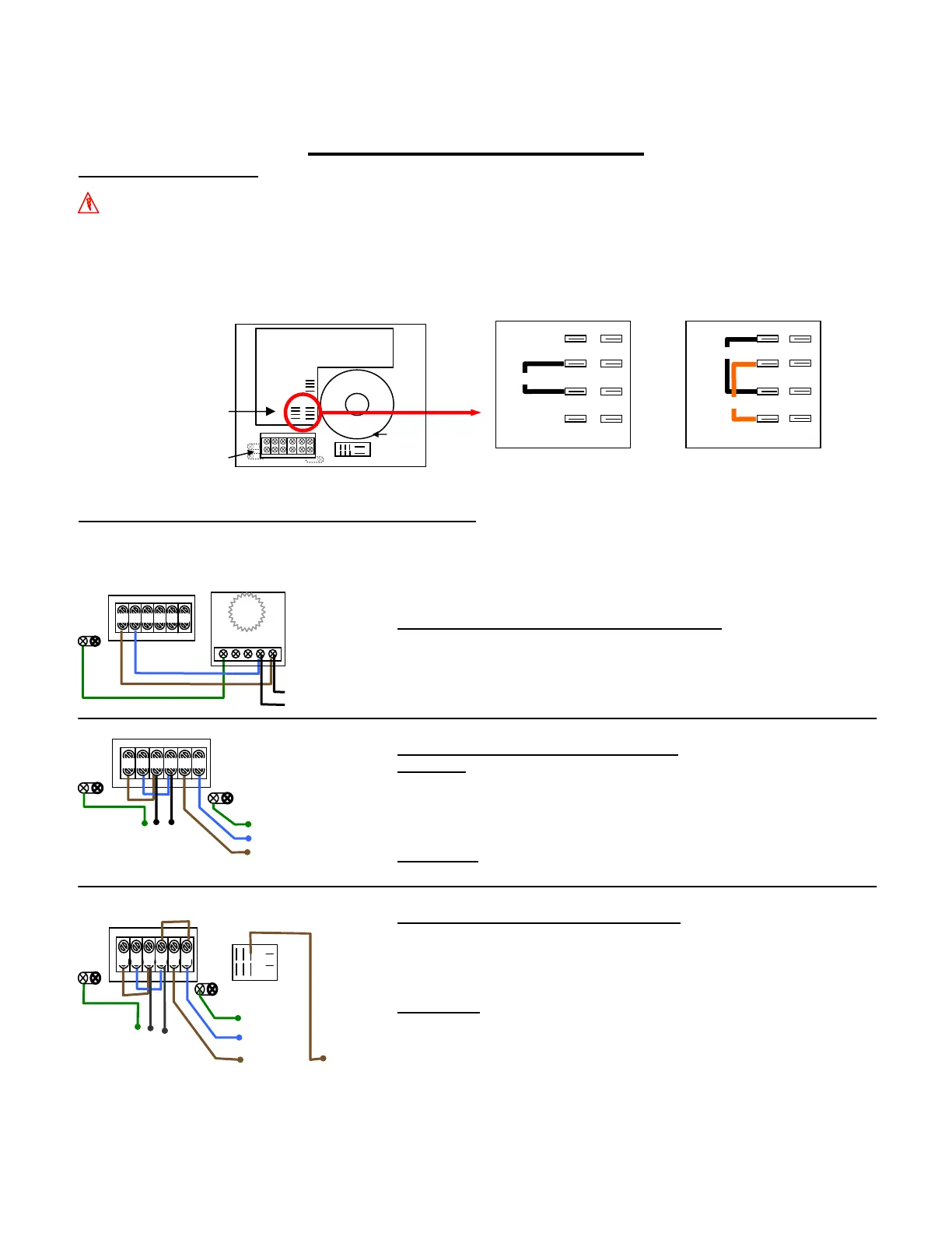
Converting from 230 VAC to 115VAC: Remove the cover (see page 12) to access the circuit board. Rewire and attach the
included *jumper as shown below on the circuit board marked “TRANSFORMER PRIMARY”.
*Jumper is provided with Power Circuit Board
your Installation Kit
Transformer
Location of the
Input Jumper
Connections
TRANSFORMER PRIMARY TRANSFORMER PRIMARY
230 VAC 115 VAC
INNER CONTROL PANEL FACTORY SETTING WIRING DIAGRAM
AC LINE IN (Wiring diagram also located on inside of cover): select the diagram that matches your application.
For 230 VAC; Brown (Br) = Line 1, Blue (Bl) = Line 2, Green w/Yellow Tracer (Gr/Yel) = Earth Ground
For 115 VAC; Brown (Br) = Line, Blue (Bl) = Neutral, Green w/Yellow tracer (Gr/Yel) = Earth Ground
(LOAD OUT)
to pump
(LINE IN)
from Circuit Breaker
Connecting Pool Pilot to One-Speed Pump
LINE-IN: Discard Factory ground (Green) wire. Cut Factory AC
wires to 5”, strip and expose ½” of wire and connect from Terminal
#1 to #3, and terminal #2 to #4. Supply new LINE-IN wires from
Circuit breaker
to Terminals #3 and #4. Ensure proper gauge wire is
used to power the pump.
LINE-OUT:
Pump is connected to Terminals #5, #6 and Ground
#2 #3
#4 #5
#6
#1
Low
Speed
Ground
Common
High
Speed
(LINE IN)
from Circuit Breaker
Connecting Pool Pilot to Two-Speed Pump
Follow instructions for One-Speed Pump LINE-IN configuration.
Note: The pump is always powered. A safety shut off (wall switch)
between the circuit breaker and control box is recommended when the
circuit breaker cannot be accessed quickly
LINE-OUT:
1) Remove Factory #4 wire from Relay and Factory #6 wire from
Terminal Strip. Cut wire in half, strip back jacket and expose
½” of wire, then jump to #6 Terminal strip.
2) Move #6 wire from Relay bottom row to the right top terminal
and connect to the Low Speed of pump.
3) High Speed = Terminal
#5
, Common = Terminal #6.
Time Clock,
Electronic
Controller Relay
or Circuit
Breaker
to pump
Connecting Pool Pilot to External Timer Setting:
Connect Factory AC wires to the LOAD SIDE or the
same location as the circulation pump wires (pump
connected to circuit breaker, time clock or electronic
Terminal Strip