6
Section 2b – INSTALLATION
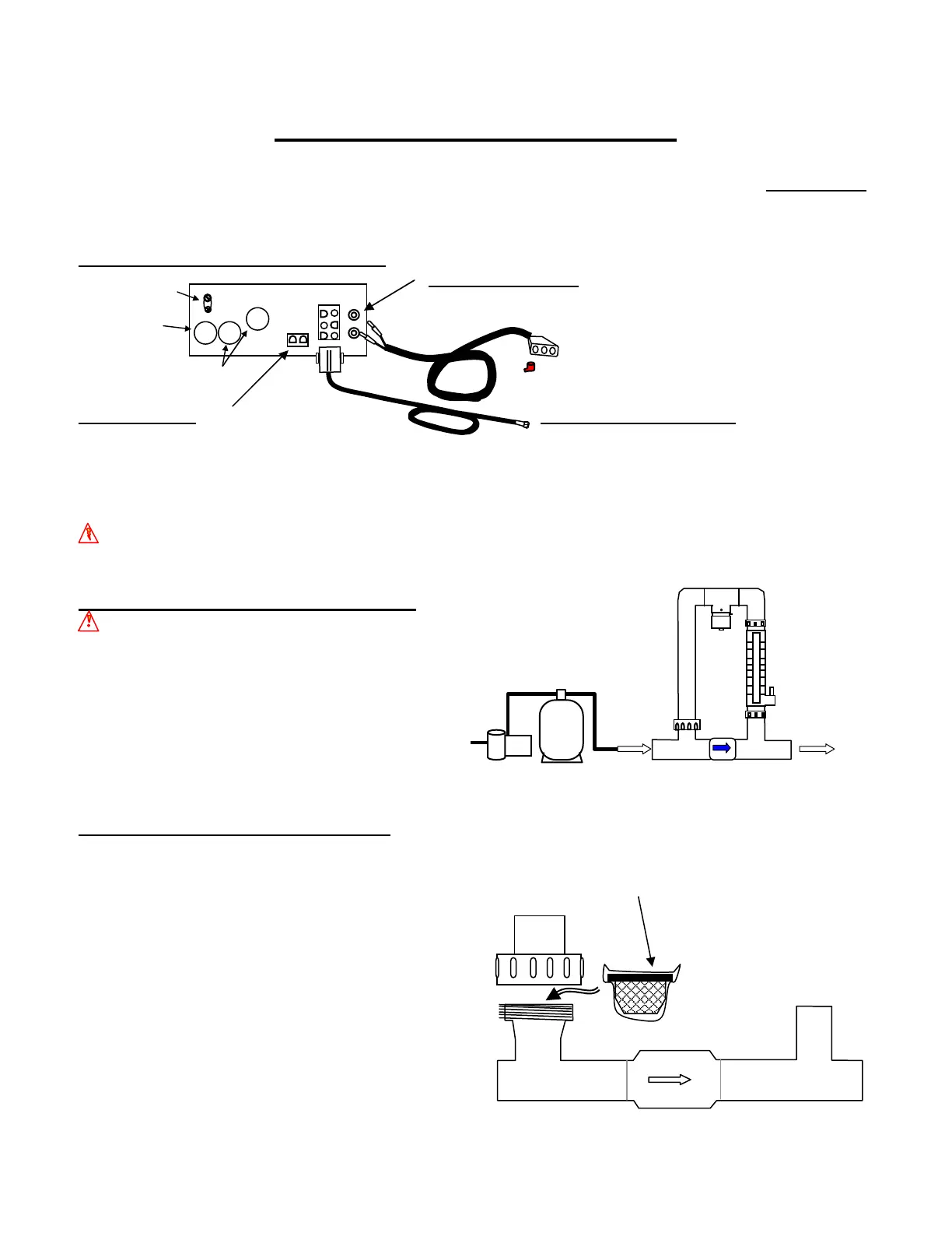
Cell and Manifold Installation
Your Pool Pilot System is adaptable for use with either the SC-36, SC-48 or SC-60 residential cell. All models come pre-
assembled with a Patented Automatic Flow Bypass Manifold Assembly. The manifold must be located as the last component
in the POOL RETURN LINE only. For pool/spa combinations or special plumbing configurations, please contact the factory
for assistance in locating the manifold.
Cell and Tri-Sensor Cord Connections
Standard Manifold Assembly (all models):
WARNING: Do not mount the manifold upside down.
Maximum flow rate 100 gpm (22.6 m³/hr). We recommend using a 3 lb
spring bypass check valve for flow rates greater than 100 gpm (22.6 m³/hr)
and plumbing it parallel to the manifold.
*One set of 68mm x 2” metric adapters (#19059)
included with European Systems.
For other plumbing configurations,
please contact the factory for assistance.
Verification of Flow Switch Protection:
It is important to verify the safe and proper operation of the
Tri-sensor’s Flow Switch protection device.
We recommend the following procedure:
Using a piece of plastic wrap (saran wrap, food wrap, or zip lock bag),
block off flow to the upper portion of the manifold.
Wrap the strainer screen with the plastic wrap and place it
back in the union and tighten. Operating the system
with this blockage should detect a LOW FLOW condition,
indicated on the digital display and activate the
“CHECK SYSTEM” light. Once verified, remove the plastic
wrap, replace the strainer screen and resume operation.
If you do not get this result, turn the output dial to (0%) OFF
and contact the factory.
CLEAN UNION
SCREEN
REGULARLY
Plastic Wrap
AC
Line
Plug
Plug
Bonding Lug
Conduit
connector
Pump conduit plugs
Red plug provided with SC-36 and
SC-48 cells to cap off one hole.
Cell Cord Connection:
(2) banana connectors plug into the (2) banana
jacks on the bottom of the Power Supply.
Tri-Sensor Cord Connection:
12’ (3.4 m) cord
connects to the Tri-Sensor Assembly with a locking
connector. Align the grove and keyway (also aligns to
directional flow arrow on the Tri-Sensor) on the connector
and twist the locking ring to ensure a proper connection.
Refer to the instructions on pages 12 & 14 for diagrams and
additional instructions.
ORP Connection:
when an ORP controller is used,
the purifier output will be automatically controlled.
Adjust the output level to 0% and connect the ORP
controller to the 2-pin connector on the Control Box
Base Plate. Although the output will displaying 0%
output, the Pool Pilot will generate purifier as
determined by the ORP controller.
WARNING: TO AVOID DAMAGE TO THE CONTROL BOX AND VOIDING THE WARRANTY, DO NOT
ENERGIZE THE ORP INPUTS! THE ORP CONNECTIONS ARE DRY CONTACT INPUTS.
To Pool
Return
Pump Filter Manifold Assembly