1/17/03
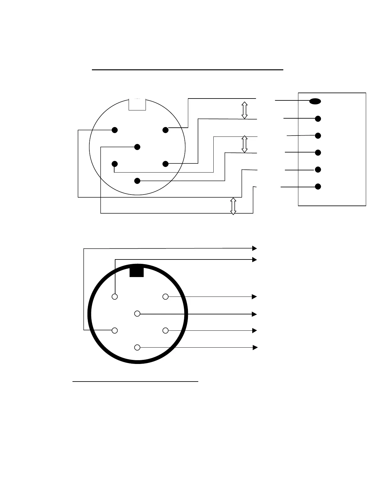
DIAGRAM “4A”
TRI-SENSOR CABLE / WIRING DIAGRAM
RED 1 Flow
FLOW
WHITE 2
5 1
BROWN 3 Salt
6 SALT
GREEN 4
4 2
BLACK 5 Temp
3 BLUE 6
TEMP.
TRI-SENSOR CABLE PLUG
(FEMALE CONNECTIONS)
FLOW
DETECTOR
1 5
TEMP
6 SENSOR
2 4
SALT
3 SENSOR
TRI-SENSOR ASSEMBLY HEAD PLUG
(MALE CONNECTIONS)
NOTE (Perform these tests on the Tri-Sensor Assembly):
- Test for continuity of the FLOW pins by attaching a continuity meter test leads to pins #1 & #2 and
manually activating the flow paddle to the center post.
- Test for continuity of the SALT pins by attaching a continuity meter test leads to pin #3 and the INSIDE
of either of the two the salt blades. Perform same test on pin #4 and the opposite blade.