Do you have a question about the Autopilot ChlorSync CS30 and is the answer not in the manual?
Explains the use of warning and caution symbols for safety instructions.
Provides contact details and website for the manufacturer.
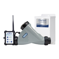
Explains the basic function of the ChlorSync® sanitizer system.
Outlines the initial steps for setting up and operating the chlorinator.
Describes the Power Center component and its role in the system.
Details the function of the flow sensor in the cell.
Explains how the salt sensor measures pool water salt levels.
Describes the role of the temperature sensor in automatic compensation.
Explains how temperature affects chlorine output and system adjustment.
Details the components and information shown on the ChlorSync® cell display.
Explains the meaning of different states of the Salt Indicator LED.
Describes the status indicated by the Cell Indicator LED.
Explains the meaning of the Flow Indicator LED states.
How to activate and deactivate the Boost Mode for increased sanitizer output.
Importance of water balance, pH, alkalinity, and hardness for pool operation.
Details the recommended types of salt for use with the system.
Explains ideal salt levels and consequences of incorrect levels.
Step-by-step instructions for adding salt to the pool water.
Information on salt loss and addition calculations.
Overview of starting up and operating the chlorinator on a daily basis.
Discusses the role of pump run time and timers for chlorinator operation.
Instructions for cleaning the ChlorSync® cell to remove scale buildup.
Instructions for safely connecting the unit to electrical power.
Guidelines for choosing a location and mounting the power center.
Solutions for when the unit's display shows no information.
Addresses low chlorine levels, dirty water, and potential causes.
Solutions for low chlorine when the pool water appears normal.
Explains the "Lo SALE" message and solid red salt LED status.
Addresses the "Add SALE" message and flashing red salt LED status.
Explains the flashing red cell LED and "CELL" display status.
Troubleshooting steps for insufficient water flow indicated by the flow LED.
Explains when the display alternates and how to exit Boost Mode.
Solutions for when the unit has no power, checking fuses and wiring.
Lists safety standards and specifications the unit conforms to.
Details the equipment's compliance with FCC regulations for digital devices.
| Pool Size | Up to 30, 000 gallons |
|---|---|
| Salt Compatibility | Yes |
| Type | Salt Chlorine Generator |
| Voltage | 120/240 VAC |
| Display | Digital |