C
Christopher WallaceSep 10, 2025
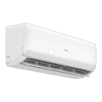
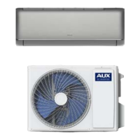
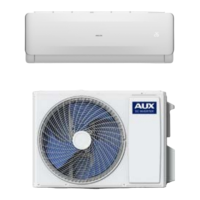
What to do if the room temperature sensor (Tico) on my AUX Inverter is faulty?
- MMandy MolinaSep 10, 2025
If your AUX Inverter displays a fault with the room temperature sensor on the indoor unit, replace the room temperature sensor.