EasyManua.ls Logo

AUX FREEDOM Series User Manual

AUX FREEDOM Series
98 pages
To Next Page IconTo Next Page
Page #1 background imageLoading...
Page #1 background image
FREEDOM SERIES
ASW-NFH3
CL80025 ~ CL80028
www.auxspain.es

Questions and Answers:

AUX FREEDOM Series Specifications

General IconGeneral
Power Supply220-240V, 50Hz
TypeSplit
Energy Efficiency Class HeatingA
FeaturesAuto Restart, Sleep Mode
Operating Temperature Range (Cooling)18°C to 43°C

Summary

Technical Information

Summary

Overview of the product series.

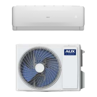
Appearance

Visual representation of indoor and outdoor units.

Model List

Catalog of available models for the series.

Product Dimensions

Indoor Unit Dimensions

Detailed drawings with measurements for indoor units.

Outdoor Unit Dimensions

Detailed drawings with measurements for outdoor units.

Specifications and Controls

Specification Sheet

Comprehensive technical data for different models.

Function and Control

Explanation of unit operations and remote controller functions.

Operation Modes

Instructions for Cooling, Heating, Fan, and Drying modes.

Battery Use and Replacement

Guide on how to install and replace remote control batteries.

System Diagrams and Electrical

Refrigerant System Diagram (Cooling Only)

Diagram and cycle explanation for cooling-only operation.

Refrigerant System Diagram (Cooling & Heating)

Diagram and cycle explanation for cooling and heating operation.

Heating Mode and Cycle

Diagram and cycle explanation for heating operation.

Indoor Unit Wiring Diagram

Electrical wiring diagram for the indoor unit.

Outdoor Unit Wiring Diagrams

Electrical wiring diagrams for outdoor units of different capacities.

Installation and Maintenance

Tools for Installation and Maintenance

Images and names of essential tools for installation and servicing.

Installation Notes

Important notices, requirements for position, height, structure, and electrical safety.

Indoor Unit Installation

Steps for installing the indoor unit, including parts check and location selection.

Indoor Unit Mounting and Piping

Procedures for mounting plate, wall-through hole, and pipeline routing.

Indoor Unit Connections and Fixing

Details on drain pipe, piping wrap, unit fixing, and electrical connection.

Outdoor Unit Installation

Steps for installing the outdoor unit, including parts and location.

Outdoor Unit Connections

Procedures for connecting pipes, wiring, and refrigerant.

Wiring Diagrams and Air Expelling

Wiring diagrams and refrigerant discharging procedure.

Post-Installation Checks

Electrical safety, installation security, water drain, and leak test procedures.

Test Operation

Procedures for test operation, including preparation and method.

Troubleshooting

Troubleshooting Guide and Error Index

General index of error codes and their reference codes.

Error Code Explanation Structure

Outlines how error codes are explained, including cause and inspection.

E0: Indoor Unit Overcurrent Protection

Explains E0 error, cause, tools, and troubleshooting steps.

E1: Indoor Unit Temperature Sensor Error

Explains E1 error, cause, tools, and troubleshooting steps.

E2: Outdoor Unit Coil Sensor Error

Explains E2 error, cause, tools, and troubleshooting steps.

E3: Indoor Unit Coil Sensor Error

Explains E3 error, cause, tools, and troubleshooting steps.

E4: Indoor Unit Motor Error (PG Motor)

Explains E4 error for PG motor, cause, tools, and troubleshooting.

E4: Indoor Unit Motor Error (DC Motor)

Explains E4 error for DC motor, cause, tools, and troubleshooting.

E5: Communication Error

Explains E5 error, cause, tools, and troubleshooting steps.

Eb: Indoor EE Failure

Explains Eb error, cause, tools, and troubleshooting steps.

F0: Outdoor Unit DC Motor Error

Explains F0 error for 3-core DC motor, cause, tools, and troubleshooting.

F1: Module Protection Error

Explains F1 error, cause, tools, and troubleshooting steps.

F2: PFC Protection Error

Explains F2 error, cause, tools, and troubleshooting steps.

F3: Compressor Out-of-Step Error

Explains F3 error, cause, tools, and troubleshooting steps.

F4: Exhaust Sensor Error

Explains F4 error, cause, tools, and troubleshooting steps.

F5: Compressor Top Head Sensor Error

Explains F5 error, cause, tools, and troubleshooting steps.

F6: Outdoor Unit Temperature Sensor Error

Explains F6 error, cause, tools, and troubleshooting steps.

F7: OVP or UVP Error

Explains F7 error, cause, tools, and troubleshooting steps.

F8: Main PCB & Module Panel Communication Error

Explains F8 error, cause, tools, and troubleshooting steps.

F9: Outdoor EE Error

Explains F9 error, cause, tools, and troubleshooting steps.

FA: Recirculated Sensor Error

Explains FA error, cause, tools, and troubleshooting steps.

P2: High-Pressure Protection

Explains P2 error, cause, tools, and troubleshooting steps.

P3: Liquid Deficiency Protection

Explains P3 error, cause, tools, and troubleshooting steps.

P4: Refrigeration Overload Protection

Explains P4 error, cause, tools, and troubleshooting steps.

P5: Exhaust Protection

Explains P5 error, cause, tools, and troubleshooting steps.

P6: Indoor High Temperature Protection

Explains P6 error, cause, tools, and troubleshooting steps.

P7: Anti-freezing Protection

Explains P7 error, cause, tools, and troubleshooting steps.

P8: Overcurrent Protection

Explains P8 error, cause, tools, and troubleshooting steps.

Function Protection Prompts

Explains various function protection prompts and their causes.

Category-L Failures Troubleshooting

Lists Category-L failures and primary troubleshooting parts.

Outdoor Unit Indicator Light Error Codes

Table showing LED indicators and corresponding error codes.

Foremost Inspecting Items

Checks for input voltage, cord connection, and other common non-error issues.

No Power Display Diagnosis

Troubleshooting steps for a unit with no power display.

Indoor Motor Not Working Diagnosis

Troubleshooting steps when the indoor motor does not operate.

Outdoor Unit Not Working Diagnosis

Troubleshooting steps when the outdoor unit does not operate.

Step Motor Not Working Diagnosis

Troubleshooting steps for the step motor controlling louvers.

Heating Mode No Hot Air Diagnosis

Troubleshooting steps when heating mode doesn't produce hot air.

Remote Control Not Working Diagnosis

Troubleshooting steps for a non-functional remote control.

Removal Procedures

Indoor Unit Removal

Step-by-step guide for disassembling the indoor unit.

Outdoor Unit Removal

Step-by-step guide for disassembling the outdoor unit.

Appendix

Sensor R-T Analysis Table (15K)

Table correlating temperature sensor resistance and MCU input voltage.

Sensor R-T Analysis Table (50K)

Table correlating temperature sensor resistance and MCU input voltage.

Related product manuals