Q
qwheelerAug 19, 2025
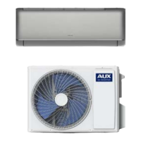
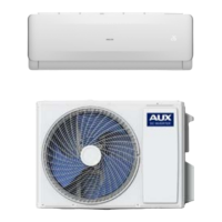
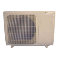
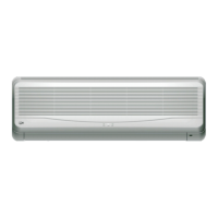
How to fix communication error between AUX Inverter outdoor and indoor unit?
- SSamantha MiddletonAug 19, 2025
If you're experiencing a communication error between the outdoor and indoor units of your AUX Inverter, the first step is to check the wiring and connections between these units to ensure they are properly connected.