EasyManua.ls Logo

AV-GAD EasyLoader AV-2004 - Keypad Wiring

Default Icon
28 pages
Print Icon
To Next Page IconTo Next Page
To Previous Page IconTo Previous Page
Loading...
4
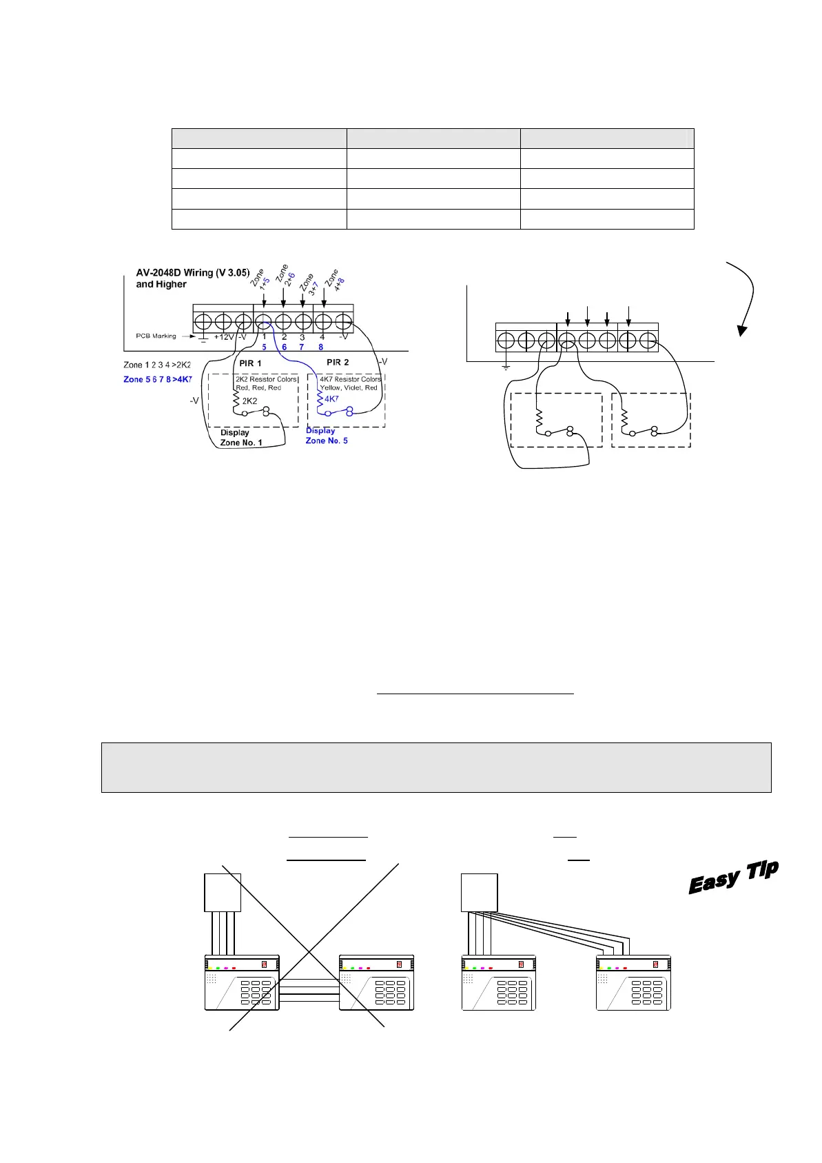
The 2.2K resistors are wired with the odd zones (1, 3, 5, 7), the 4.7K are wired with the even
zones (2, 4, 6, 8) as table below shows, for latest AV-2048 starting version 3.05.
Terminal wire No.
Resistor 2.2K
Resistor 4.7K
1
Zone No. 1
Zone No. 5
2
Zone No. 2
Zone No. 6
3
Zone No. 3
Zone No. 7
4
Zone No. 4
Zone No. 8
Version 3.00 to 3.04
Figure 1: Optional zones wiring in AV-2048D from version 3.05 (left side)
Very Slow Response Zone
This feature entered to AV-2048D PRO Version 3.08. At 032 select the zone to act “Very Slow”,
at address 059 set the time in minutes, at 075-4 enable the “Very Slow” feature.
3. KEYPAD WIRING
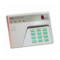
Up to two AV-701T/TI or four AV-702 Keypads can be connected to AV-2004/48 Control Panel.
When few keypads are connected, wire each one directly to the panel, not from one keypad to the
other. Refer to drawing in next page.
Important Note: Up to two (2) AV-701T/TI or four (4) AV-702 Keypads can be connected to
AV-2004/48 Alarm Control Panel
When using few keypads connect them in parallel. Each keypad has four terminal wires:
(+) Power, connect to + Aux. Power
System Data, connect to OR
() Power, connect to Aux. Power
System Strobe, connect to YE
*
7
4
1
0
8
5
2
#
9
6
3
Siren
Shunt
Display Status
Delay
Delete
Chime
Test Program Reset
Shunt
Telephone
ARMED STATUS SHUNT FIRE
ZONE
DISPLAY
EASYLOADER AV-701AV-GAD AV-GAD EASYLOADER AV-701
FIRESHUNTSTATUSARMED
Test
Delete
Delay
Siren
1
4
7
*
DISPLAY
ZONE
Telephone
Shunt
ResetProgram
Chime
StatusDisplay
Shunt
3
6
9
#
2
5
8
0 *
7
4
1
Siren
Delay
Delete
Test
ARMED STATUS SHUNT FIRE
EASYLOADER AV-701AV-GAD
DISPLAY
ZONE
Telephone
Shunt
ResetProgram
Chime
StatusDisplay
Shunt
3
6
9
#
2
5
8
0
AV-GAD EASYLOADER AV-701
FIRESHUNTSTATUSARMED
Test
Delete
Delay
Siren
1
4
7
* 0
8
5
2
#
9
6
3
Shunt
Display Status
Chime
Program Reset
Shunt
Telephone
ZONE
DISPLAY
Panel
Panel
Wrong Wiring Correct Wiring
Figure 2: Wiring more than one keypad
For example, if 50
entered to address
059 the response
time is 50 x 4 = 200
seconds (three
minutes and 20
seconds). Maximum
value is 63.
-V
-V
432
1
+12V
PIR 1
PIR 2
2K2
4K7
Display
Zone 1
Display
Zone 2
Z
o
n
e
1
+
2
Z
o
n
e
3
+
4
Z
o
n
e
5
+
6
Z
o
n
e
7
+
8
-V
AV-2048/D Wiring
(by Default)
4K7 Resistor Colors
Yellow, Violet, Red
2K2 Resistor Colors
Red, Red, Red
-V

Related product manuals