21
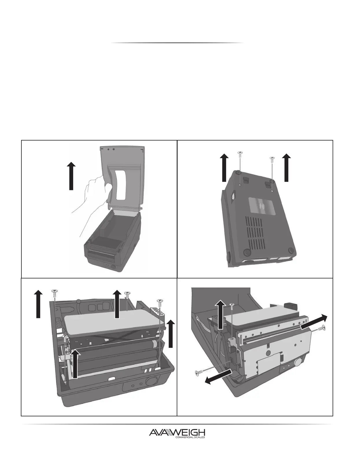
CUTTER INSTALLATION
1. Turn off the printer power, unplug the power cable and USB/Serial cable.
2. Remove the top cover.
3. Remove (2) screws at base housing.
4. Remove the whole Print Head Assembly by releasing (4) screws at its feet.
5. Add a cutter baby board on J5 on the main board.
6. Secure (3) attached screws for the cutter.
7. Plug the cutter's connector into the PCB's header connector (J3).
8. Reinstate the Print Head Assembly by securing the (4) screws.
9. Click back the middle cover.
10. Secure (2) screws back at base housing.
11. Install the top cover.