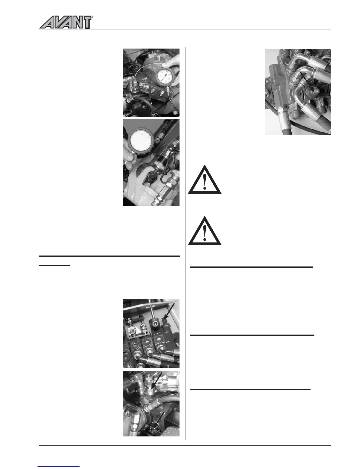
Drive pressure: There are
two checking points, on top of
the variable displacement pump
and under the variable displa-
cement pump. One tells the
pressure for forward driving,
the other for reverse driving.
When checking the pressure
the wheels must be locked e.g.
with the parking brake, engine
must run with full revs when
pressing the two drive pedals.
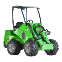
On models 520+, 523+,
528+ and 530+ the pressure
for boom lifting and auxiliary
hydraulics is checked and
adjusted separately. Pressure
for lifting is checked from the
manometer fitting, which is
located under the front cover
plate, beside the steering hyd-
raulic motor. Auxiliary hydrau-
lics pressure is checked by
mounting the manometer in
the female auxiliary hydraulics quick coupling, with
full revs and by turning the aux. hydraulics control lever.
It is recommended pressures should only be checked
by a competent and experienced technician
. Call
your AVANT dealer if you need assistance.
9. ADJUST PRESSURE OF HYDRAULIC
SYSTEM
If the pressure of hydraulic system does not seem to
be correct or pressure check indicates that the pressure
is wrong, it can be adjusted. Following table shows
pressure adjusting points.
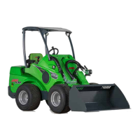
Boom lifting/auxiliary
hydraulics: Pressure is adjusted
from the pressure relief valve
at the main control valve.
Pressure relief valve is the first
section of the control valve, in
front of the first valve block.
Adjust by turning the hexagonal
head screw which is under the
cap.
Drive pressure: Can not be
adjusted. If the pressures are
clearly wrong one must change
the pressure relief cartridges
which have fixed pressure
setting. They are located beside
the pressure checking points.
The cartridge on top of the
pump is for driving forward,
under the pump for reverse
driving.
On models 520+, 523+,
528+ and 530+ the pres-
sure for boom lifting is adjus-
ted from the pressure relief
valve at the main control
valve, in the same way as
mentioned above.
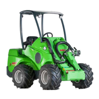
Pressure for auxiliary hydrau-
lics is adjusted from the
shock valve on the valve
segment of aux. hydraulics
pump selection (1-pump ,
2-pump), see picture. The
adjustment screw is under
the cap, adjustment with hexagonal head key.
10. GREASING OF THE MACHINE
Greasing of pivot points is very important in order to
avoid wear. Most of the greasing points are on the
loader boom. There are 15 grease nipples altogether
on a machine with standard boom and 21 grease
nipples on a machine with telescopic boom. The
picture on page 24 shows the location of grease nipples.
11.-18. SERVICE, PETROL ENGINE
AVANT 513 is equipped with the Honda GX390
petrol engine. Service and maintenance instructions
for this engine can be found in the Honda Operators
Manual supplied with the loader.
19.-32. SERVICE, DIESEL ENGINE
Loader models AVANT 514, 520, 520+, 523+,
528+ and 530+ are equipped with a Kubota diesel
engine (see technical specification sheet for the engine
type of each model). Service and maintenance
instructions for the engines can be found in the Kubota
Operators Manual supplied with the loader.
Maintenance instructions
23
500 Series
WARRANTY DOES NOT
COVER DAMAGES CAUSED
BY EXCESSIVE HYDRAULIC
PRESSURE.
NEVER EXCEED THE RECOM-
MENDED HYDRAULIC PRES-
SURE SETTINGS. EXCESSIVE
HYDRAULIC PRESSURE WILL
DAMAGE THE HYDRAULIC
PUMPS, CYLINDERS, AND
HYDRAULIC MOTORS.