Hardware included with ERS 3510GT and ERS 3510GT-PWR+ model switches:
•
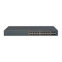
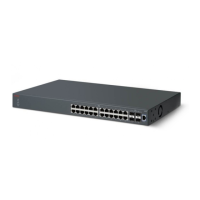
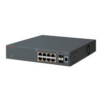
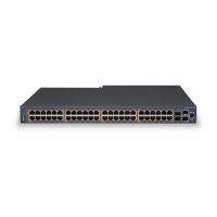
Avaya Ethernet Routing Switch 3500 Series
• Rubber footpads
• AC power cord (Note: a power cord is not included for the A variant of the switch)
• Base Software License Kit
• Screws (2) and wall anchors (2) for wall mounting
The following procedure provides instructions for installing the switch on a table or shelf.
Important:
Allow at least 2 inches (5.1 cm) on each side of the switch for proper ventilation and at least
5 inches (12.7 cm) at the back of the switch for power cord clearance.
Procedure
1. Attach the rubber feet at the marked locations.
2. Set the switch on a table or shelf.
Installation preparation
February 2013 5

 Loading...