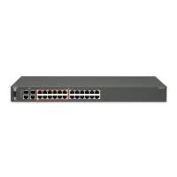
4. Once the switches are joined together, fold the hinged bracket inward.
5. Perform one of the following
• To connect two ERS 3510GT or two 3510GT-PWR+ switches together use
the rear bracket as shown below, with four M4 pan head screws to secure the
switches at the rear. Once the rear bracket has been installed, the switches
can be installed in the rack.
• To connect one ERS 3510GT switch and one ERS 3510GT-PWR+ switch
together use the offset rear bracket with four M4 pan head screws to join the
switches at the rear. Once the rear bracket has been installed, the switches
can be installed in the rack.
Installation preparation
Regulatory Information 5.0 February 2012 29

 Loading...