Table 12: DC power supply specifications
Description DC-DC-12V-300 W
Output power 300 W
Input voltage 48 V DC
Input current 10 A
Output voltage 12 V DC
Output current 25 A
Mean time between failures 293,000 hours
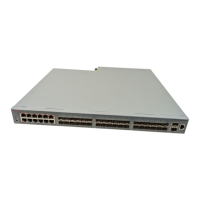
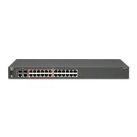
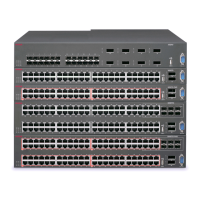
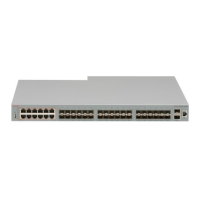
Installing the Avaya Virtual Services Platform 4000 power
supply
You must install at least one power supply before using the switch. Avaya VSP 4000 models
support two field replaceable external power supplies. If supported, you can install an optional
second power supply for redundancy, load sharing, or to provide additional PoE+ power budget.
Perform the following procedure to install an external power supply into your switch.
Note:
Avaya VSP 4000 hardware can vary. This procedure only applies to hardware models with field
replaceable power supplies.
1. If a blanking plate covers the required power supply slot, remove the blanking plate before
attempting to insert the power supply.
2. Insert each power supply into a rear power supply slot.
3. Verify that each power supply is fully seated in the slot. Secure the power supply with the
two thumb screws.
Note:
The switch chassis can prevent an incorrect installation of a power supply. If you insert a
power supply upside down, it will not fully insert and the thumb screws will not engage.
4. Once you install a power supply, you can proceed with connecting AC power.
Note:
Do not connect an AC and DC power supply in the same chassis. Load sharing may be
affected.
Installing the Avaya VSP 4000 4450GSX series
November 2016 Installing Avaya Virtual Services Platform 4450GSX-PWR+ Switch 30
Comments on this document? infodev@avaya.com
 Loading...