107
9 Interface Specifications
9.1 Interface Information
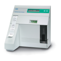
The AVL 9120, 30, 40, 80 and 81 analyzers are equipped with a standard
serial interface output. This interface output is intended to be used with
standard commercially available computer systems.
The data transmitted through the serial interface port employs the ASCII code.
The serial interface is terminated on the rear cover with a 9-pin male DB-9
connector.
The signal levels are as follows:
- Binary 1 = -12V to -3V
- Binary 0 = +3V to +12V
Two stop bits follow the eight data bits to complete the 10 bit word.
The baud rate is set at 9600 Baud fixed.
The maximal recommended cable length is 40 feet.
The pin assignment is as follows:
pin 1...sample ground...GND
pin 2...receive data....RxD
pin 3...send data.......TxD
pin 4...NC
pin 5...signal ground...GND
pin 6...NC
pin 7...RTS
pin 8...CTS
pin 9...NC
(NC=Not Connected)

 Loading...