4000 Opacity Measuring Chamber Type A
Service Manual 6-3
6.2 Upgrading an AVL DiGas 4000 to an
AVL DiCom 4000
A trained service engineer can upgrade the instrument with the following components:
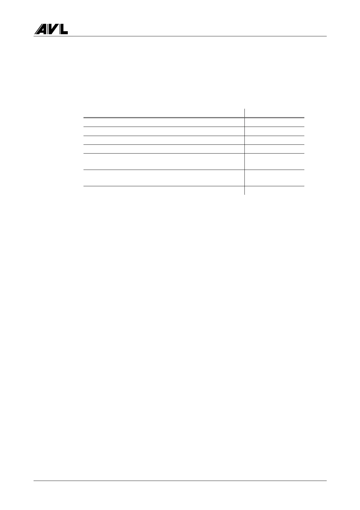
Component AVL ident. no.
Chamber Adapter Board 435 BB0814
Sensor Unit Cable (control cable) BV2122
Heating Cable BV2123
Control Cable Socket EU0180
Fixing elements
(for mounting the control socket on the rear panel)
EU1705
2 self-tapping screws 2.9 × 9.5 mm
(for mounting the heating socket on the rear panel)
DS0978
AVL DiCom 4000 sticker ZB1804
If there are no cutouts in the rear panel for the two sockets (control cable and heating
cable), you will need the ZG1940 rear panel. These cutouts have already been prepared in
most rear panels and simply need to be pushed out of the panel.
Conversion instructions
• Open the instrument completely
• Remove speed/angle board
(4 Phillips screws on the outside, one hexagon nut on the inside)
• Insert 435 Chamber Adapter Board at slots J4, J6, J10 and J14 of the main board
• Push the prepared cutouts out of the rear panel.
If there are no prepared cutouts, you must used Rear Panel ZG1940.
• Mount the two cables with the sockets on the rear wall.
• Connect the two cables to the 435 Chamber Adapter Board.
• The fuses of the mains switch group must be changed - for AVL DiCom 4000, 3.15 A
slow-blow fuses must be used
• Change the sticker on the rear panel and enter the new fuse rating.
 Loading...