Evaluation Unit AVL 4000
4-4 Service Manual
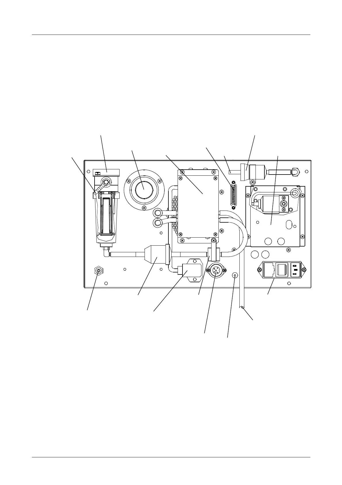
4.1.3 Pneumatics Rear Panel / 4-/5-Gas Measuring Instruments
Unit (5-Gas Option)
The entire pneumatic unit is mounted on the rear wall. The 4-gas measuring instruments
unit is screwed to the rear panel.
The condensate trap, particulate filter, O
2
(NO- 5-gas option) sensor and pump are
mounted directly on the outside of the rear panel.
Fig. 4-2
Inlet for
calibration gas
O
2
sensor
NO sensor (option)
Zero gas
inlet
(pure air)
Control cable connect.
(to opacity measuring
chamber type A only)
Particulate filterConnection for
probe
Activated carbon filter
Pump
Condensate trap
Analog output
(analog signal of exhaust opacity;
0…5 V
=
0…100 % opacity)
Condensate
outlet
Heating cable connection
(opacity measuring chamber type A)
or control cable connection
(opacity measuring chamber type 4000)
Power supply
for pump
Mains connection
with ON/OFF switch
and fuse box
Non-return
valve
Condensate filter
 Loading...