Opacity Measuring Chamber Type A AVL 4000
6-10 Service Manual
4
7
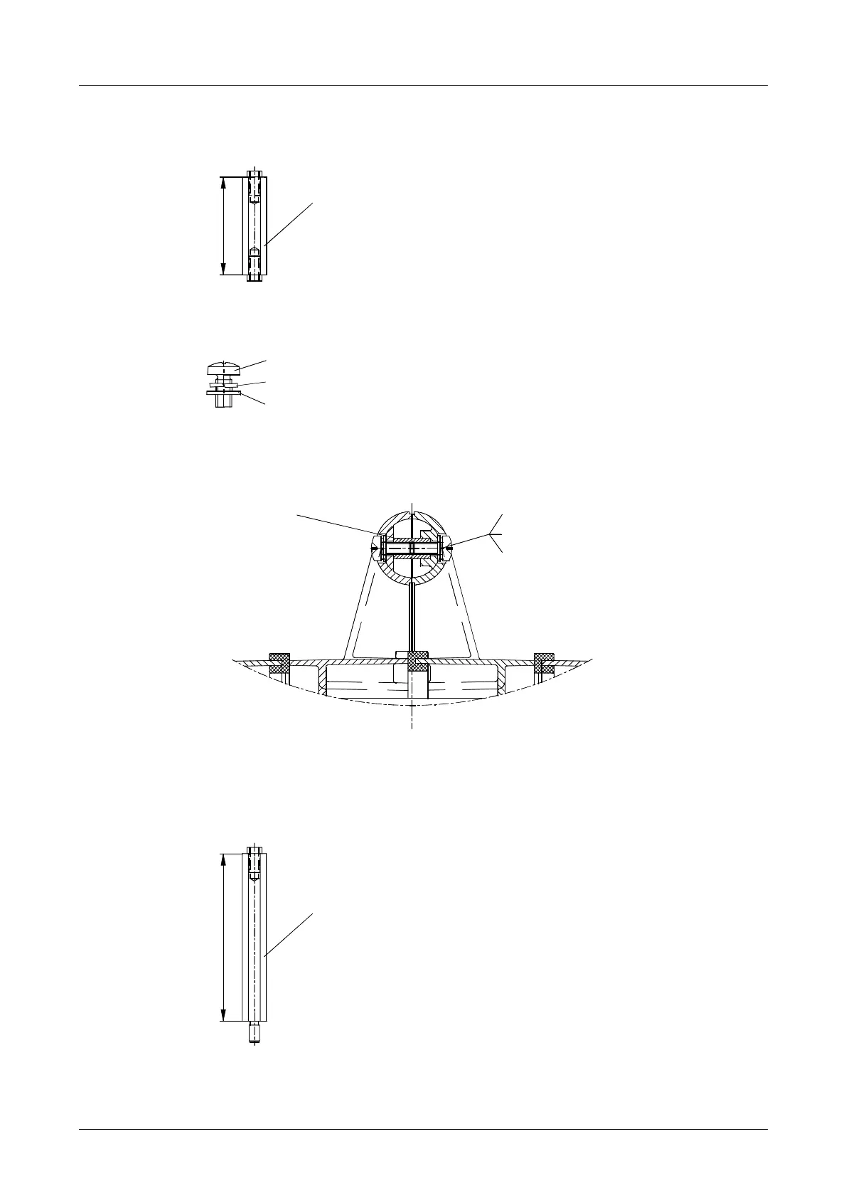
Fig. 6-13
• Undo the two screws on the measuring chamber handle.
Fig. 6-14
Detail: Screw joint in handle
DS1172
DZ0567
DZ0253
4x
4x
4x
EP0297 2x
Fig. 6-15
• Stand the measuring chamber upright.
It should now be possible to undo 9 stud bolts (B) by hand on the exhaust gas inlet
side (half-shell 2).
8
0
.
5
Fig. 6-16
2 pcs.
While undoing these bolts, apply
counterpressure to the bolts
underneath them (located
between the two half-shells and
reached via access point "X").
Stud bolt C YM2681
Spacer pin
Stud bolt B YM2680 9 pcs.
DS1172 Oval-head screw M5x10
DZ0567
DZ0253
Oval-head screw M5x10
 Loading...