Opacity Measuring Chamber Type A AVL 4000
6-14 Service Manual
− Carefully extract the heating block from the inside of the half-shell.
Heating block complete BO1248
The heating block you now have in front of you consists of the following components:
− 1 heating block YM2675 (incl. connection cable and connector)
− 1 face plate YM2676
− 1 heating element 230 V/500 W ZH0061
− 2 oval-head screws (M4x6) for fastening the face plate to the heating block.
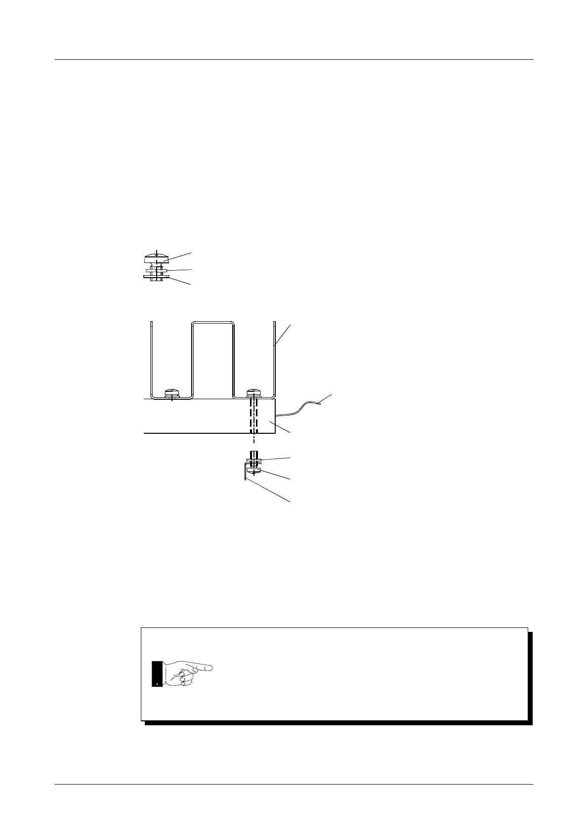
Fig. 6-22
Fig. 6-23
After re-installing the heating block:
• Glue the temperature sensor back into position
(see Section 6.8 Temperature Sensor).
• Re-connect the power cable.
• Re-connect the protective conductor.
DS1041
DZ0558
DZ0251
After working on the heating blocks, always carry out a function
check (see Operating Manual).
Face plate
Connection plate
Contact disc DZ0549
Oval-head screw M4x10 DS0162
Faston connector 6.3 EU0520
 Loading...