4000 Evaluation Unit
Service Manual 4-63
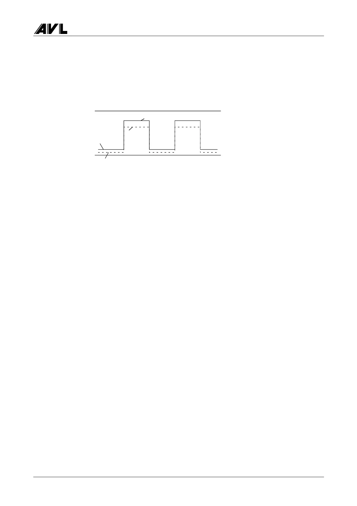
System voltage
System voltages RC and RF are clocked voltages (i.e. square-wave signals). The system
voltages are represented as RC HIGH / RC LOW and RF HIGH / RF LOW and are
somewhere between 0 and 5 V.
5 V
0 V
RC HIGH
RC LOW
RF HIGH
RF LOW
Fig. 4-9
The RC voltage (receiver voltage) is caused by the light of the LEDs that is radiated into
the smoke channel of the opacity measuring chamber and received at the end by the
photoelectric cell.
The RF voltage (reference voltage) is caused by the light radiated from the back of the
LEDs, i.e. unaffected by the smoke channel, and received by the reference signal
photocell. Since the light radiated from the back of the LEDs is proportional to the light
radiated to the front and since the light sources (i.e. LEDs) are clocked (i.e. switched on
and off), it is possible to correct a measurement signal (RC) that is affected by external
influences (e.g. temperature, outside light) even during a measurement.
The measurement accuracy of a system is no longer assured when the system is outside
tolerance:
RC HIGH > 5 V
RF HIGH > 5 V
RC LOW > 0.8 V
RF LOW > 0.8 V
RC HIGH - RC LOW < 1.75 V
Lamp status
The lamps can be switched on and off separately by pressing the LAMP key.
Valve voltage
This displays the valve switching time (1…2.5 s) when it changes to another position
(CALIBRATION, MEASUREMENT).
Setting
The valve position (CALIBRATION, MEASUREMENT) can be changed by pressing the
VALVE key.
 Loading...