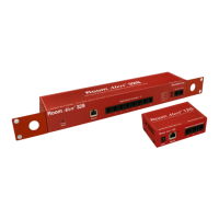
AVTECH Software Inc. 15
Room Alert Signal Tower Conguration And Setup Screens
Digital Sensors
The ‘Sensors’ section is used to congure sensor labels and to set thresholds for when alerts will be
generated. Sensor labels can be up to 14 characters in length. AVTECH recommends modifying the
sensor labels to reect the location of the sensor to make it easier to know the current reading in a
specic location with a quick glance at the Status screen.
High and low thresholds can be dened for each sensor. If the current value rises above the high
threshold or falls below the low threshold, an alert will be generated. When the current value returns to a
normal state, the alert will clear and a follow-up alert will be sent.
The sensors can be calibrated by entering correction values in the ‘Adjust’ eld for each temperature
sensor. To adjust the temperature down, enter a minus (-) sign before the value (i.e. -5). Each row
displays the type of sensor that is connected, as well as the currently congured temperature scale.
Thresholds should be entered in the same temperature scale as currently congured.
Digital Temperature Sensor Digital Temperature/Humidity Sensor
Switch Sensors
Alert thresholds for switch sensors connected to the Room Alert Signal Tower ID Box are set by
specifying either ‘Closed’ or ‘Open’. Please refer to the documentation received for any switch sensors