S – 150 Controller User Manual
MKTF – 429-A 25 08/16
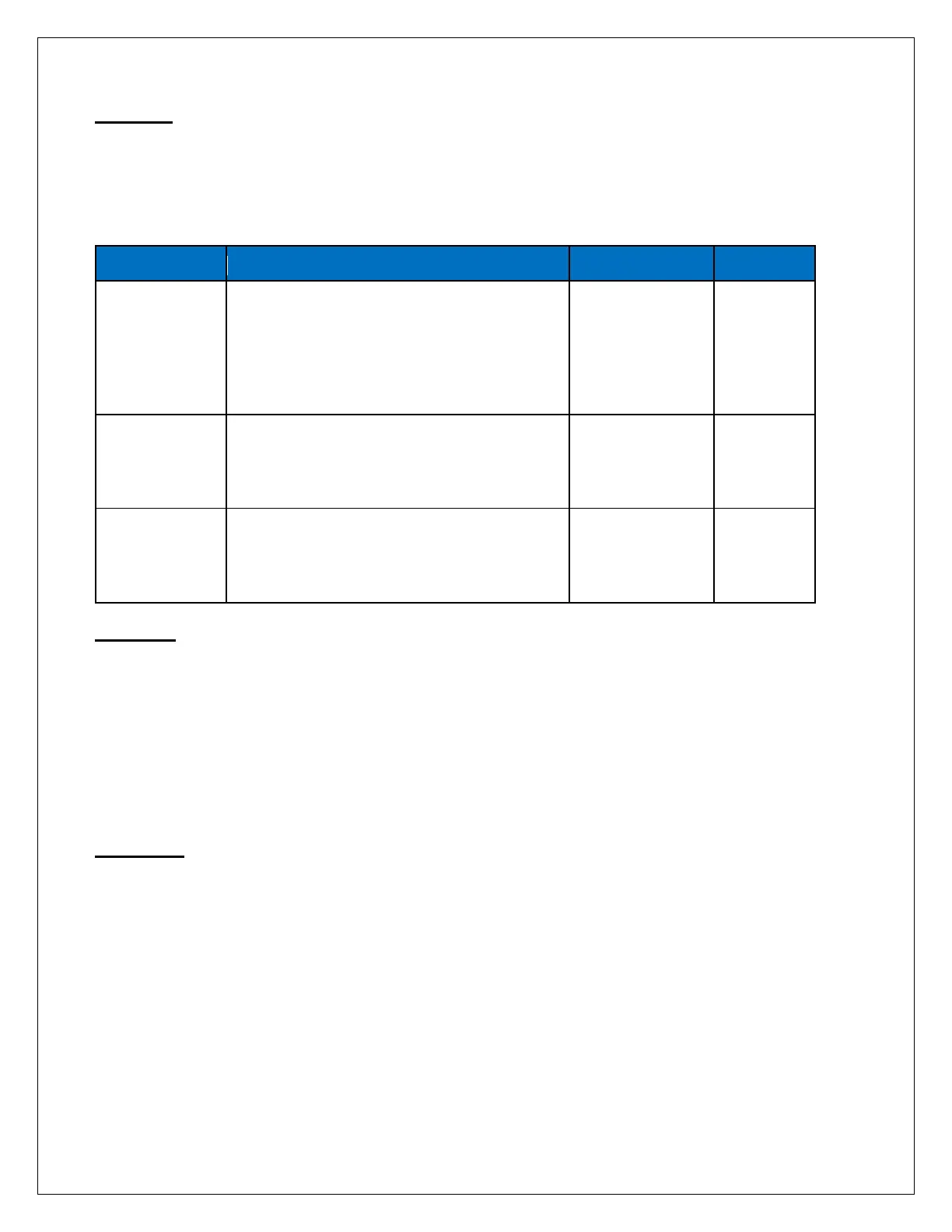
Setpoints
When the expander is installed, 3 additional Setpoints are provided to allow features of the expander to
be changed. Refer to the Displaying or Changing Setpoints section of the manual on page 14 for
information on changing the Setpoints. The additional Setpoints are listed below.
Operation
When the TDS / Conductivity expander is installed, the reading will be shown on line two and will
alternate every three to four seconds with the hours and temperature. If the percentage of rejection
display is enabled, it will be shown on line two with the second TDS / Conductivity reading.
If the C2 limit is enabled, and the second TDS / Conductivity reading exceeds the limit programmed the
C2 Limit Setpoint for the delay programmed in the TDS / Conductivity Delay Setpoint, the alarm lamp
will light and the HI TDS / Conductivity 2 warning message will show on the display. This warning will
clear when the second TDS / Conductivity drops below the Setpoint.
Calibration
Refer to Figure 6 for adjustment location. To calibrate the second TDS / Conductivity, place the cell in a
known standard solution. Adjust the span adjustment for the correct reading. If the cell is installed, the
unit can be calibrated by taking a sample of the water and testing it with a known, good meter. Adjust
the span control until the reading matches the meter.
Selects range of TDS / Conductivity
monitor 0 – 50, 1 – 100, 2 – 250, 3 – 500,
4 – 1,000, 5 – 2,500, 6 – 5,000, 7 – 10,000
NOTE: If this Setpoint is changed, the unit
must be recalibrated and range
components may need to be changed.
When this value is met or exceeded, the
alarm lamp will light and high TDS /
Conductivity will show on the display. To
ppm
If the second TDS / Conductivity is used to
monitor feedwater, programming this
Setpoint to one allows the percentage of
rejection to be displayed.