S – 150 Controller User Manual
MKTF – 429-A 9 08/16
TDS / Conductivity Cell Wiring
For accurate TDS / Conductivity readings, the cell should be installed in a tee fitting where a continuous
flow of water passes over the cell and no air can be trapped around the cell. Refer to Figure 5 for example
installation. The cell is connected with five wires to terminal strip P10. Connect each colored wire to the
terminal labeled with the same color.
Switch Inputs
Switch inputs are connected to P9. The connections for these inputs are not polarity sensitive and can
be connected to either terminal. The switch inputs should be dry contact closures only.
NOTE: Applying voltage to these terminals will damage the controller. The switches can be either
normally open or normally closed in any combination. The switch connected to an input that is configured
as normally open must be open for the unit to run. The switch connected to an input that is configured
as normally closed must be closed for the unit to run. The Switch Select Setpoint allows each input to be
configured as normally open or normally closed. The Switch Select Setpoint is defaulted to zero, which
programs all inputs as normally open. This means that all switch inputs must be open for the unit to run.
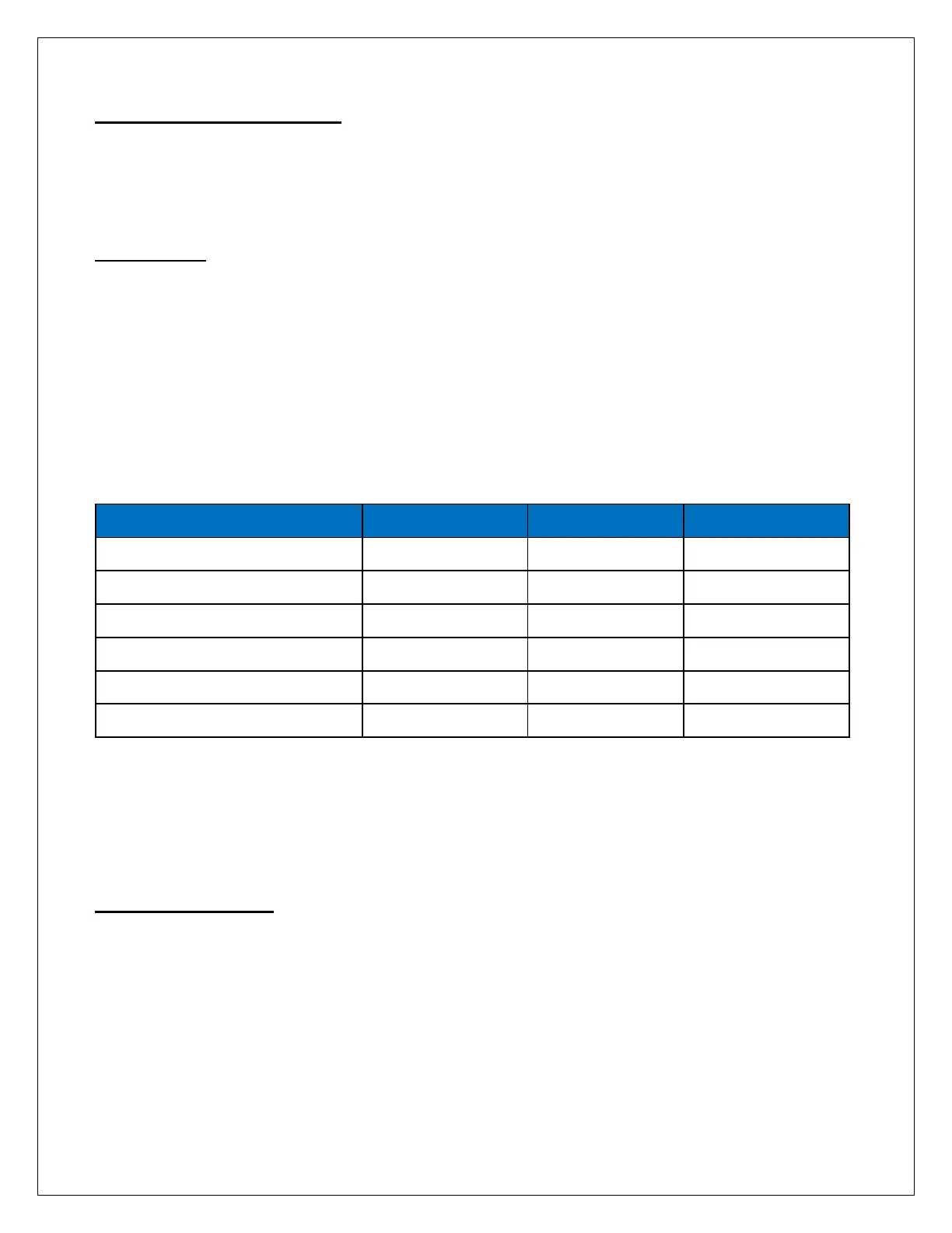
Table 1 lists the values used to program the Setpoint to configure the inputs.
TABLE 1. Switch Select Programming
Select the type of switch used for each input and put that number in the value column. Add the values
and program the total in the Switch Select Setpoint. For example, if the pressure fault and tank low
inputs were normally closed and all others normally open, the value programmed in the Switch Select
Setpoint would be 17(1 + 16).
Pressure Fault Switch
On systems where a low feed pressure shutdown is required, a feed pressure switch can be connected
to the pressure fault input of P9. If a high pump pressure shutdown is required, a high pressure switch
can be connected to this input. If both low feed pressure and high pump pressure shutdown are
required, both switches can be connected to this input. Both switches must be either normally open or
normally closed to operate properly.