Do you have a question about the AXIOMTEK CAPA848 and is the answer not in the manual?
Details key features of the CAPA848 board, including processor, memory, ports, and form factor.
Provides detailed technical specifications for the CAPA848 board's CPU, memory, I/O, and connectivity.
Lists essential software utilities required for the CAPA848 board, such as drivers.
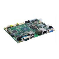
Details the physical dimensions and mounting hole locations for the CAPA848 board.
Illustrates the component placement and connector locations on the CAPA848 board's top and bottom views.
Explains the function and configuration of various jumpers on the CAPA848 board for system setup.
Provides a comprehensive list and description of all onboard connectors on the CAPA848 board.
Details pin assignments and signals for the front panel connector, including power and reset buttons.
Specifies pinout for the inverter connector, used for LCD panel backlight control.
Details pin assignments for the LVDS connector, used for LCD display interface.
Lists pin assignments for the audio connector, supporting microphone and line-level audio.
Describes the pinout for the digital I/O port connector, used for automation control.
Details the pin configuration for the fan connector, used for system cooling.
Specifies the pinout for the SMBus connector, used for system management communication.
Details pin assignments for USB ports 2 and 3 on the CAPA848 board.
Lists pin assignments for the HDMI connector, supporting video and audio output.
Details pin assignments for the COM3 and COM4 serial ports.
Specifies pinout for the SATA power connector, used for HDD power supply.
Details pin assignments for the VGA connector used for display output.
Describes the ATX power connector for supplying power to the board's components.
Specifies pinout for the SATA connector, used for connecting storage devices.
Details pin assignments for USB port 1, used for peripherals like keyboards and mice.
Lists pin assignments for the RJ-45 Ethernet port for network connectivity.
Details pin assignments for the COM1 serial port (RS-232/422/485).
Specifies pin assignments for the COM2 serial port (RS-232/422/485).
Describes the connector for the CMOS battery, maintaining BIOS settings.
Details pinout for the half-size PCI-Express Mini Card slot.
Specifies pinout for the full-size PCI-Express Mini Card slot.
Details the pinout for the SIM card socket, used for 3G wireless applications.
Describes the Intel Celeron N2807 processor and its impact on system performance and compatibility.
Provides information about the AMI Plug and Play BIOS used on the CAPA848 board.
Details the system memory specifications, including socket type, capacity, and supported RAM types.
Lists the I/O port addresses used by the Intel Celeron N2807 processor for communication.
Details the interrupt request (IRQ) mappings for various system devices.
Presents the memory mapping list for the system's hardware components.
Explains how to enter and access the AMI BIOS setup utility for system configuration.
Describes the hotkeys and navigation methods used within the BIOS setup utility.
Details the options available in the BIOS Main Menu, including BIOS information and system language.
Covers configuration settings for CPU and system devices accessible via the Advanced Menu.
Allows configuration of advanced chipset settings, including North and South Bridge parameters.
Details options for setting system passwords and security configurations.
Explains how to configure boot options, including boot device priority and timeout settings.
Describes options for saving configuration changes, discarding them, and exiting the BIOS setup.
Provides step-by-step instructions for installing the Intel Chipset Device Software.
Details the process for installing the Intel Graphics Driver for display functionality.
Explains how to install the Intel Network Connections (Ethernet) driver.
Provides instructions for installing the Realtek High Definition Audio Driver.
Guides users through the installation of the Intel Trusted Execution Engine.
Details the installation process for the Intel Sideband Fabric Device Driver.
Explains the function of the watchdog timer for system auto-resetting.
Provides an example of configuring the watchdog timer using a debug tool.
Describes the onboard digital I/O capabilities, including default settings.
Offers an example of configuring digital I/O ports using a debug tool.
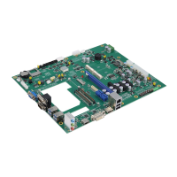
| Form Factor | Mini-ITX |
|---|---|
| CPU Socket | LGA1151 |
| Max Memory | 32GB |
| Expansion Slots | 1 x PCIe x16 |
| Dimensions | 170 mm x 170 mm |
| Video Output | 1 x HDMI, 1 x DisplayPort, 1 x VGA |
| Operating Temperature | 0°C to 60°C |
| USB Ports | 4 x USB 2.0 |
| Ethernet | 2 x Gigabit Ethernet |
| CPU Support | 8th/9th Gen Intel® Core™ i7/i5/i3, Pentium® & Celeron® Processors |