EasyManua.ls Logo

AXIOMTEK CAPA848 - 2.4.2 Inverter Connector (CN2); 2.4.3 LVDS Connector (CN3)

AXIOMTEK CAPA848
84 pages
Print Icon
To Next Page IconTo Next Page
To Previous Page IconTo Previous Page
Loading...
CAPA848 Capa Board
Board and Pin Assignments 13
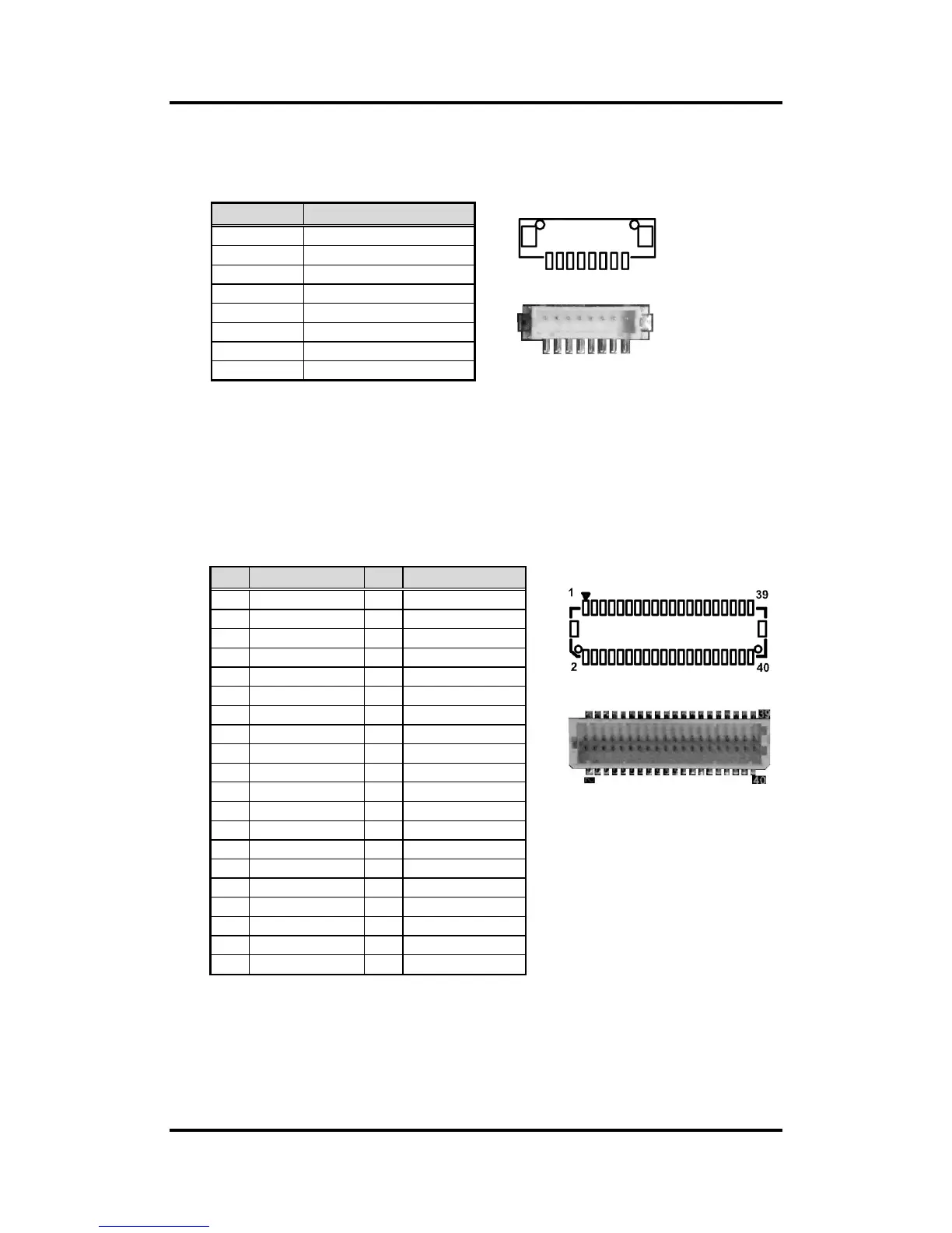
2.4.2 Inverter Connector (CN2)
This is a DF13-8S-1.25C 8-pin connector for inverter. We strongly recommend you to
use the matching DF13-8S-1.25C connector to avoid malfunction.
8 1
2.4.3 LVDS Connector (CN3)
This board has a 2x20-pin connector for LVDS LCD interface. It is strongly
recommended to use the matching JST SHDR-40VS-B connector for LVDS interface.
Pin 1~6 VCCM can be set to +3.3V, +5V or +12V by setting JP1 or JP6 (see section
2.3.1).
18-bit single channel
Pin
Signal
1
VBL1 (+12V level)
2
VBL1 (+12V level)
3
VBL2 (+5V level)
4
VBL_ENABLE
5
GND
6
GND
7
GND
8
VBL Brightness Control
Pin
Signal
Pin
Signal
1
VCCM
2
VCCM
3
VCCM
4
VCCM
5
VCCM
6
VCCM
7
N.C.
8
N.C.
9
GND
10
GND
11
N.C.
12
N.C.
13
N.C.
14
N.C.
15
GND
16
GND
17
N.C.
18
N.C.
19
N.C.
20
N.C.
21
GND
22
GND
23
Channel A D0-
24
N.C.
25
Channel A D0+
26
N.C.
27
GND
28
GND
29
Channel A D1-
30
N.C.
31
Channel A D1+
32
N.C.
33
GND
34
GND
35
Channel A D2-
36
Channel A CLK-
37
Channel A D2+
38
Channel A CLK+
39
GND
40
GND

Table of Contents