CAPA848 Capa Board
10 Board and Pin Assignments
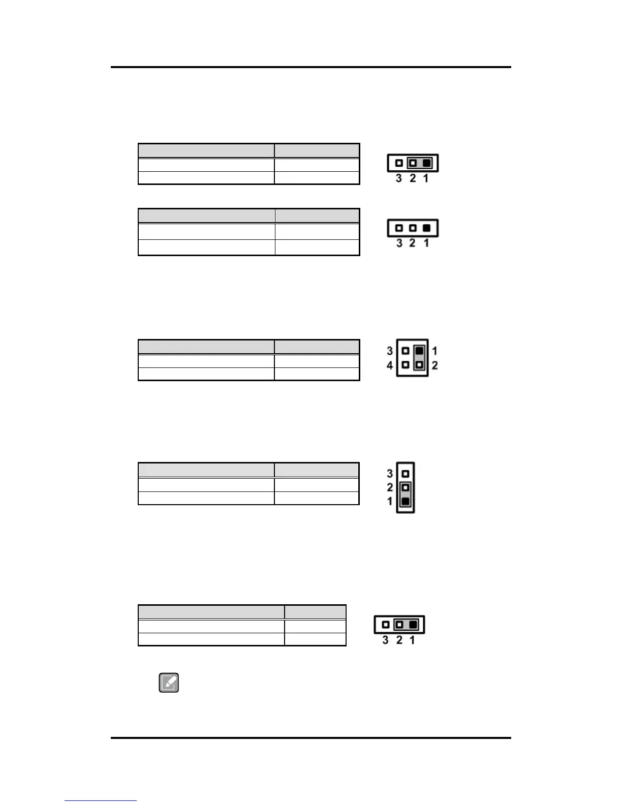
2.3.1 LVDS Voltage Selection (JP1 and JP6)
The board supports voltage selection for flat panel displays. Use these jumpers to set
LVDS connector (CN3) pin 1~6 VCCM to +3.3V, +5V or +12V. To prevent hardware
damage, before connecting please make sure that input voltage of flat panel is correct.
JP1
JP6
2.3.2 LVDS Brightness Control Mode Setting (JP3)
The JP3 enables you to select PWM or voltage control mode for inverter connector
(CN2). These two control modes are for adjusting the brightness of LVDS panel.
2.3.3 Restore BIOS Optimal Defaults (JP4)
Put jumper clip to pin 2-3 for a few seconds then move it back to pin 1-2. Doing this
procedure can restore BIOS optimal defaults.
2.3.4 Auto Power On (JP10)
If JP10 is enabled for AC power input, the system will be automatically power on without
pressing soft power button. If JP10 is disabled for AC power input, it is necessary to
manually press soft power button to power on the system.
This function is similar to the feature of power on after power failure,
which is controlled by hardware circuitry instead of BIOS.
 Loading...