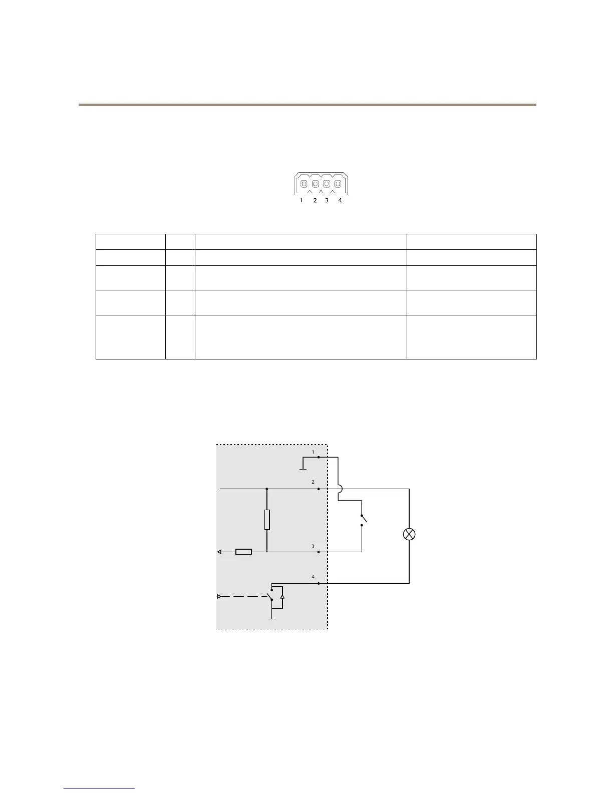
Foranexamplediagram,seeConnectionDiagramsonpage58.
FunctionPinNotes
Specications
0VDC(-)
1
0VDC
DCoutput
2
Canbeusedtopowerauxiliaryequipment.
Note:Thispincanonlybeusedaspowerout.
12VDC
Maxload=15mA
DigitalInput
3
Connecttopin1toactivate,orleaveoating(unconnected)
todeactivate.
0tomax30VDC
DigitalOutput
4
Connectedtopin1whenactivated,oating(unconnected)
whendeactivated.Ifusedwithaninductiveload,e.g.arelay,
adiodemustbeconnectedinparallelwiththeload,for
protectionagainstvoltagetransients.
0tomax30VDC,opendrain,
100mA
ConnectionDiagrams
I/OConnector