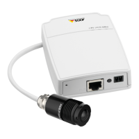
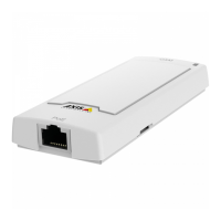
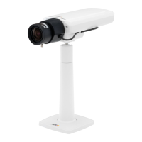
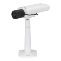
AXISP12NetworkCameraSeries
•TheStatusLEDcanbeconguredtoashwhileaneventisactive.
•TheStatusLEDcanbeconguredtoashforidentifyingtheunit.GotoSetup>System
Options>Maintenance.
ConnectorsandButtons
Forspecicationsandoperatingconditions,seepage15.
NetworkConnector
RJ45EthernetconnectorwithPoweroverEthernet(PoE).
NO NO
NO
TICE TICE
TICE
Theproductshallbeconnectedusingashieldednetworkcable(STP).Allcablesconnecting
theproducttothenetworkshallbeintendedfortheirspecicuse.Makesurethatthe
networkdevicesareinstalledinaccordancewiththemanufacturer’sinstructions.For
informationaboutregulatoryrequirements,seeElectromagneticCompatibility(EMC)2.
I/OConnector
Usewithexternaldevicesincombinationwith,forexample,tamperingalarms,motiondetection,
eventtriggering,timelapserecordingandalarmnotications.Inadditiontothe0VDCreference
pointandpower(DCoutput),theI/Oconnectorprovidestheinterfaceto:
•Digitaloutput–ForconnectingexternaldevicessuchasrelaysandLEDs.Connected
devicescanbeactivatedbytheVAPIX®ApplicationProgrammingInterface,output
buttonsontheLiveViewpageorbyanActionRule.Theoutputwillshowasactive
(shownunderSystemOptions>Ports&Devices)ifthealarmdeviceisactivated.
•Digitalinput–Analarminputforconnectingdevicesthatcantogglebetweenanopen
andclosedcircuit,forexample:PIRs,door/windowcontacts,glassbreakdetectors,
etc.Whenasignalisreceivedthestatechangesandtheinputbecomesactive(shown
underSystemOptions>Ports&Devices).
PowerConnector
2-pinterminalblockforpowerinput.UseaSafetyExtraLowVoltage(SELV)compliantlimited
powersource(LPS)witheitheraratedoutputpowerlimitedto≤100Woraratedoutputcurrent
limitedto≤5A.
RJ12Connector
TheRJ12connectorisusedforconnectingthesensorunittothemainunit.
ForinformationonhowtoshortenthesensorunitcableseeShortenSensorUnitCable.
14