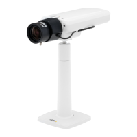
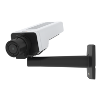
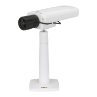
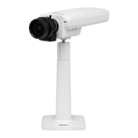
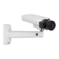
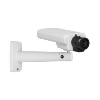
AXISP12NetworkCameraSeries
ConnectionDiagrams
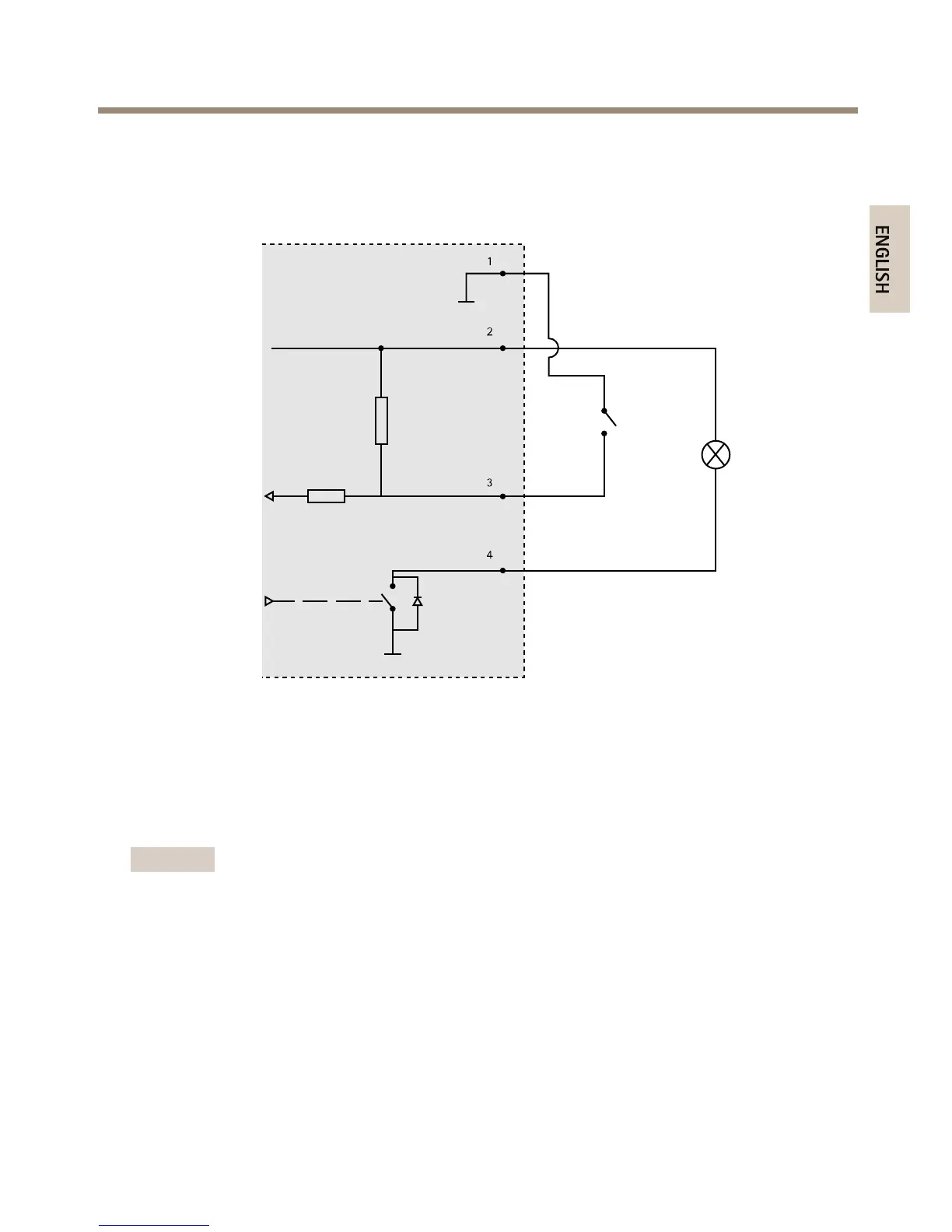
I/OConnector
1
0VDC(-)
2
DCoutput3.3V,max50mA
3
Digitalinput0tomax40VDC
4
Digitaloutput0tomax40VDC,opendrain,100mA
InstalltheHardware
Important
Thecasingofthemainunitisnotapprovedforoutdooruse-theproductmayonlybe
installedinindoorenvironments.
Makeanoteoftheserialnumber(S/N)locatedontheproductlabel.Thisnumbermayberequired
duringinstallation.
ThemainunitcanbemountedonaDINrailorusingthesuppliedmountingrail.
1.Ifusingthemountingrail,fastenitwithscrewstothewallorceiling,usingscrewsand
plugsappropriateforthewall/ceilingmaterial.Notethedirectionofthetwotabsonthe
rail,thetabsalignwiththeuppersideofthemainunit.
17