AXISP33NetworkCameraSeries
Specifications
Foraudioin,theleftchannelisusedfromastereosignal.
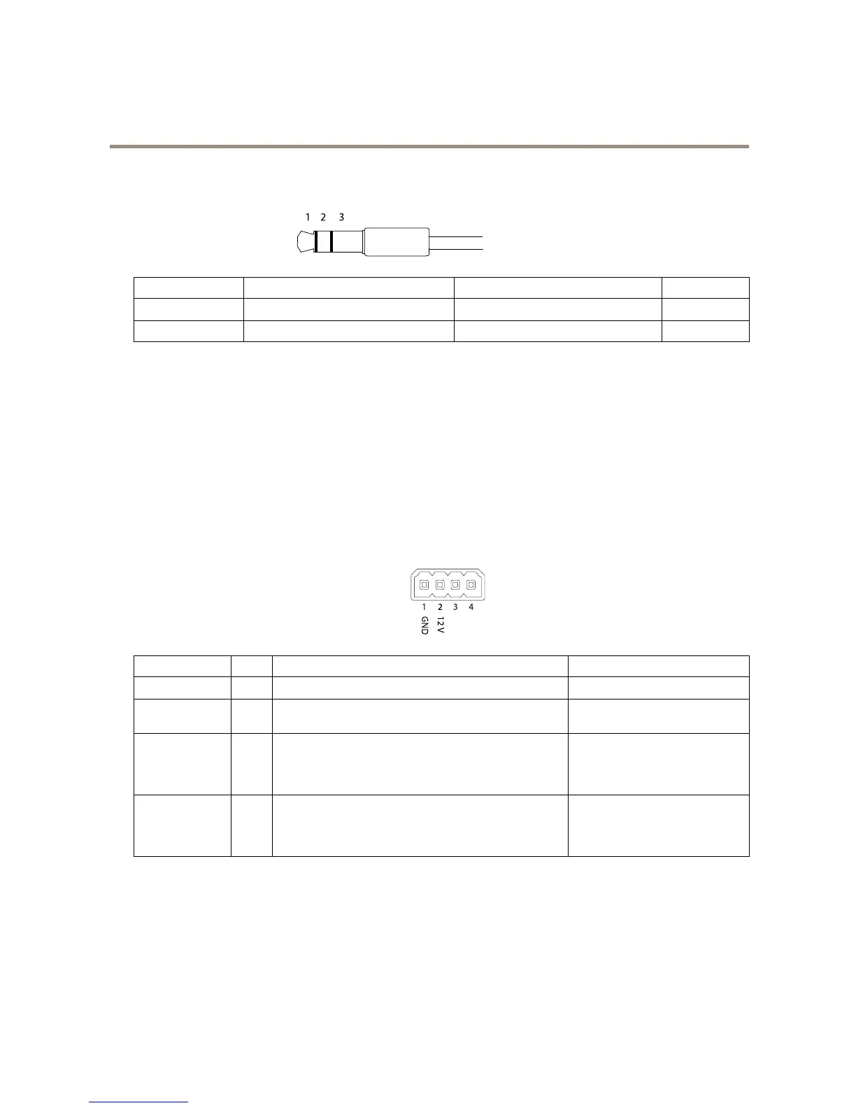
3.5mmaudioconnectors
(stereo)
1Tip2Ring
3Sleeve
AudioInput
Microphone/Linein
Microphonebiasvoltage
Ground
AudioOutput
Lineout,monoLineout,mono
Ground
Theinternalmicrophoneisusedbydefault;theexternalmicrophoneisusedwhenconnected.Itispossibletodisabletheinternal
microphonebyconnectingaplugtothemicrophoneinput.
I/Oconnector
UsetheI/Oconnectorwithexternaldevicesincombinationwith,forexample,motiondetection,eventtriggering,andalarm
notications.Inadditiontothe0VDCreferencepointandpower(DCoutput),theI/Oconnectorprovidestheinterfaceto:
Digitaloutput-ForconnectingexternaldevicessuchasrelaysandLEDs.ConnecteddevicescanbeactivatedbytheVAPIX®
ApplicationProgrammingInterfaceorintheproduct’swebpage.
Digitalinput-Forconnectingdevicesthatcantogglebetweenanopenandclosedcircuit,forexamplePIRsensors,door/window
contacts,andglassbreakdetectors.
Supervisedinput-Enablespossibilitytodetecttamperingonadigitalinput.
4-pinterminalblock
FunctionPinNotes
Specications
0VDC(-)
1
DCground0VDC
DCoutput
2
Canbeusedtopowerauxiliaryequipment.
Note:Thispincanonlybeusedaspowerout.
12VDC
Maxload=25mA
DigitalInputor
SupervisedInput
3
Connecttopin1toactivate,orleaveoating(unconnected)
todeactivate.Tousesupervisedinput,installend-of-line
resistors.Seeconnectiondiagramforinformationabouthow
toconnecttheresistors.
0tomax30VDC
DigitalOutput
4
Connecttopin1toactivate,orleaveoating(unconnected)
todeactivate.Ifusedwithaninductiveload,e.g.,arelay,
connectadiodeinparallelwiththeload,toprotectagainst
voltagetransients.
0tomax30VDC,opendrain,
100mA
23