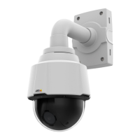
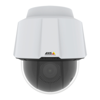
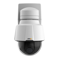
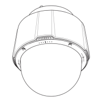
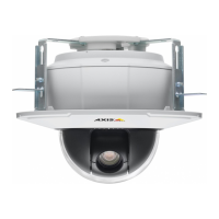
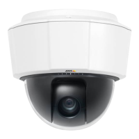
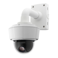
AXISP5635–EPTZDomeNetworkCamera
TechnicalSpecifications
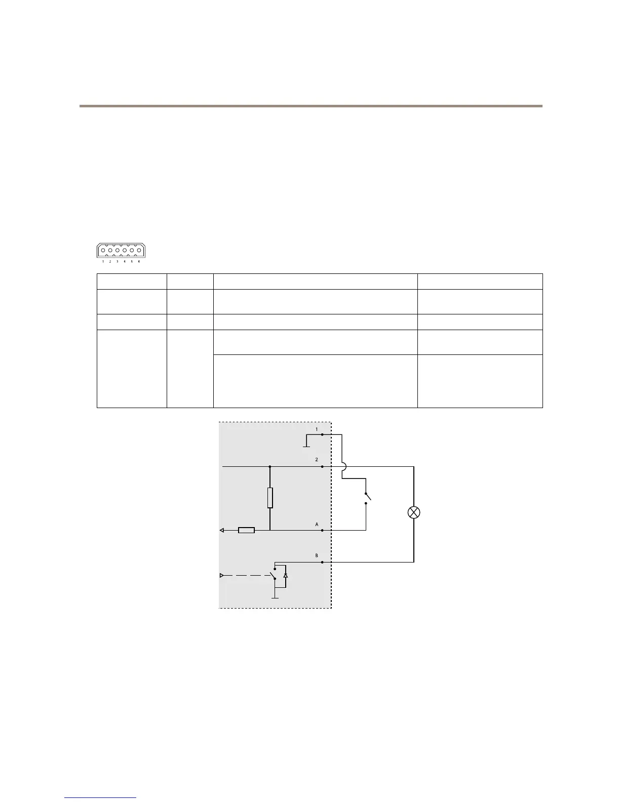
I/Oconnector-6–pinterminalblock.Usewithexternaldevicesincombinationwith,forexample,tamperingalarms,motion
detection,eventtriggering,timelapserecordingandalarmnotications.Inadditiontothe0VDCreferencepointandpower(DC
output),theI/Oconnectorprovidestheinterfaceto:
•Digitaloutput—ForconnectingexternaldevicessuchasrelaysandLEDs.Connecteddevicescanbeactivatedbythe
VAPIX®ApplicationProgrammingInterface,outputbuttonsontheLiveViewpageorbyanActionRule.Theoutput
willshowasactive(shownunderSystemOptions>Port&Devices>PortStatus)ifthealarmdeviceisactivated.
•Digitalinput—Analarminputforconnectingdevicesthatcantogglebetweenanopenandclosedcircuit,for
example:PIRs,door/windowcontacts,glassbreakdetectors,etc.Whenasignalisreceivedthestatechangesand
theinputbecomesactive(shownunderSystemOptions>Port&Devices>PortStatus).
FunctionPinNotes
Specications
DCOutput
2
Canbeusedtopowerauxiliaryequipment.
Note:Thispincanonlybeusedaspowerout.
12VDC
Maxload=50mA
GND
1
Ground
Digitalinput–Connecttopin8toactivate,orleave
oating(unconnected)todeactivate.
0tomax30VDC Congurable
(InputorOutput)
3–I/O1
4–I/O2
5–I/O3
6–I/O4
Digitaloutput–Connectedtopin8whenactivated,
oating(unconnected)whendeactivated.Ifusedwithan
inductiveload,e.g.arelay,adiodemustbeconnected
inparallelwiththeload,forprotectionagainstvoltage
transients.
0tomax30VDC,opendrain,
100mA
1
GND
2
DCoutput12V,max50mA
A
I/Oconguredasinput
B
I/Oconguredasoutput
Axis10-pinPush-PullSystemConnector(soldseparately)
WhenconnectingexternalequipmenttotheAxisproduct,anAxis10-pinPush-PullSystemConnector(soldseparately)isrequiredin
ordertomaintaintheproduct’sIPrating.
67