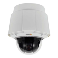
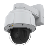
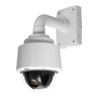
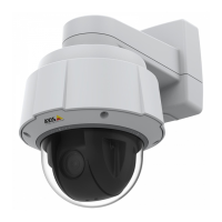
AXIS Q60-S Series
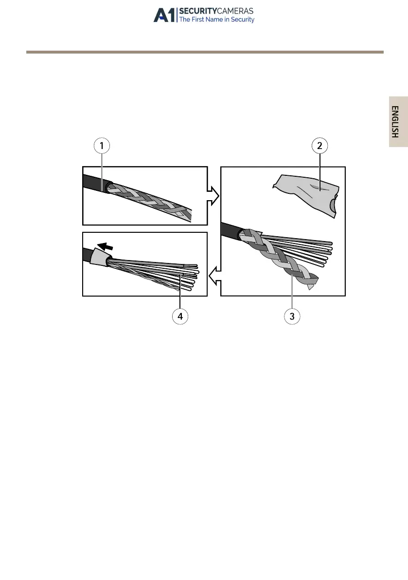
4. Strip off 40 mm (1.57 in) of the multi-connector cable jacket.
5. Leave the braided shield intact, but cut off 30 mm (1.18 in) of the outer foil shield.
6. Fold back the leftover outer foil shield and twist the braided shield into a coil.
7. Cut off about 7–8 mm (0.27–0.32 in) of the Ethernet wire foil shields.
8. Strip off about 4–5 mm (0.16–0.20 in) of the power wire jackets.
1
Multi-connector cable jacket
2
Outer foil shield
3
Braided shield
4
Ethernet wire foil shield (2x)
9. Connect the network and I/O wires to the internal network and I/O connectors. Open
the lid, insert the wires and close.
10. Connect the ground and power wires to the power connector (DC output).
25
Available from A1 Security Cameras
www.a1securitycameras.com email: sales@a1securitycameras.com
 Loading...