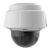
AXISQ60Series
I/Oterminalconnector-Usewithexternaldevicesincombinationwith,forexample,tampering
alarms,motiondetection,eventtriggering,timelapserecordingandalarmnotications.Inaddition
tothe0VDCreferencepointandpower(DCoutput),theI/Oconnectorprovidestheinterfaceto:
•Digitaloutput—ForconnectingexternaldevicessuchasrelaysandLEDs.
ConnecteddevicescanbeactivatedbytheVAPIX®ApplicationProgramming
Interface,outputbuttonsontheLiveViewpageorbyanActionRule.Theoutput
willshowasactive(shownunderSystemOptions>Port&Devices>Port
Status)ifthealarmdeviceisactivated.
•Digitalinput—Analarminputforconnectingdevicesthatcantogglebetween
anopenandclosedcircuit,forexample:PIRs,door/windowcontacts,glass
breakdetectors,etc.Whenasignalisreceivedthestatechangesandtheinput
becomesactive(shownunderSystemOptions>Port&Devices>PortStatus).
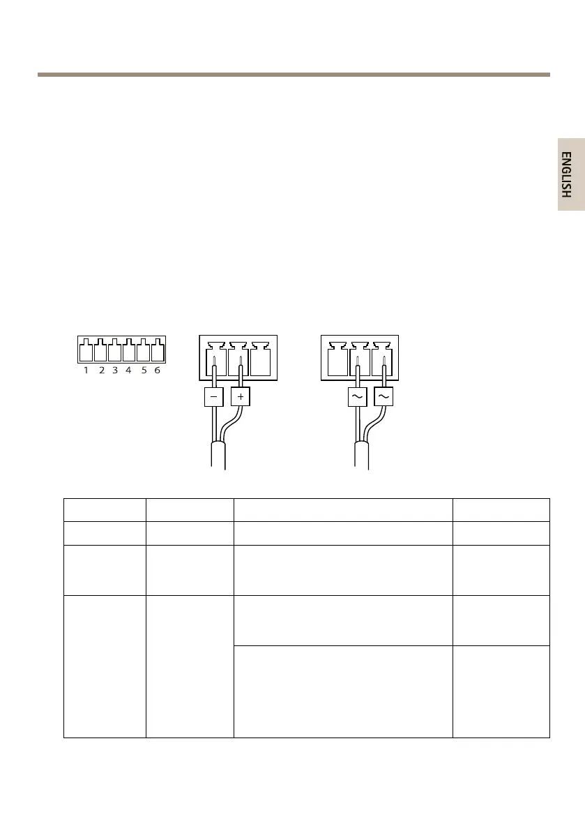
I/Oconnector
DCpowerinputACpowerinput
FunctionPinNotes
Specications
0VDC(-)
1
DCoutput
2
Canbeusedtopowerauxiliaryequipment.
Note:Thispincanonlybeusedaspower
out.
3.3VDC
Maxload=
250mA
Digitalinput–Connecttopin1to
activate,orleaveoating(unconnected)
todeactivate.
0tomax40VDC
Congurable
(Inputor
Output)
3–6
Digitaloutput–Connectedtopin1when
activated,oating(unconnected)when
deactivated.Ifusedwithaninductive
load,e.g.arelay,adiodemustbe
connectedinparallelwiththeload,for
protectionagainstvoltagetransients.
0tomax40VDC,
opendrain,
100mA
25
 Loading...